Create SolidWorks 3D to 2D Drawing Faster for Manufacturing
12 min
- How to Make a Drawing in SolidWorks
- How Manual Drawing Creation Slows Engineers Down
- Automating SolidWorks 3D to 2D Drawing for Repetitive Workflows
- Manual vs Automated SolidWorks Drawing Workflows
- FAQs About SolidWorks 3D to 2D Drawing
- Conclusion: Making a Drawing in SolidWorks
Every manufactured part starts as a 3D model, but the shop floor still runs on drawings. A SolidWorks 3D to 2D drawing is the manufacturing document created from a 3D part or assembly model. The model carries the shape; the drawing explains how that shape should be made and measured. Engineers use these drawings to communicate dimensions, tolerances, and production notes to the machinist, the quality inspector, and the supplier.
A drawing is not a separate sketch of the part. SOLIDWORKS Help describes drawings as linked documents, so changes to the part or assembly can update the drawing document. The engineer still has to review dimensions, references, notes, and views before release.
This guide covers the standard SolidWorks 3D to 2D drawing workflow first, then the bottlenecks that appear when the same drawing work is repeated across many similar parts. Automation is treated as support, not a shortcut around review. For high-volume cases, JLCCAN Auto-Drawing can help create the first drawing structure faster, while final checking remains engineering work.
Key Takeaways
- A good SolidWorks 3D to 2D drawing starts before the drawing sheet even opens; the model orientation, feature order, and sketch references decide how clean the drawing will be.
- Model Items can automatically pull most dimensions from the part, which saves significant time on dimensioning work.
- Manual drawing work becomes slow when the same view layout and annotation pattern must be repeated across many similar parts.
- Auto-drawing tools are useful for repetitive plate-type and block-type parts, but the released drawing still needs a human engineering review.
How to Make a Drawing in SolidWorks
Making a drawing in SolidWorks is faster when the model already has stable references, sensible origin placement, and manufacturing intent in the feature order. The fastest SolidWorks drawings I have prepared were not the ones with the fewest dimensions. They were the ones where the model tree and view direction made the drawing predictable. Use the workflow below as a practical SolidWorks drawing tutorial rather than a button-by-button manual.
Make Drawing from Part SolidWorks: Start with the Right File
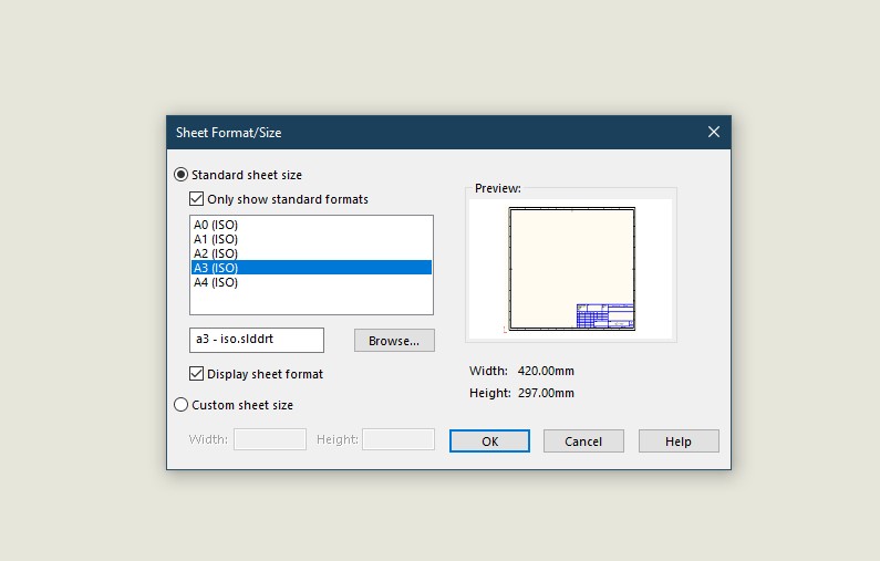
Start from the finished part or assembly and create the drawing from the model. The search phrase make drawing from part SolidWorks usually points to this exact workflow: open the model, create the drawing, then choose the template and sheet format. SOLIDWORKS Help lists Make Drawing from Part/Assembly as the standard model-based route.
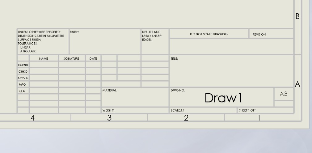
The template controls title block fields, projection standard, units, default fonts, line weights, and common notes before a single view is inserted. Choose sheet size from the largest view and expected annotation load, not only the physical part size. For CNC-bound work, pair the drawing with a clean CAD export process; the JLCCNC guide on preparing CAD files for CNC machining is a useful related checklist.
Place the Main Views Before Adding Dimensions
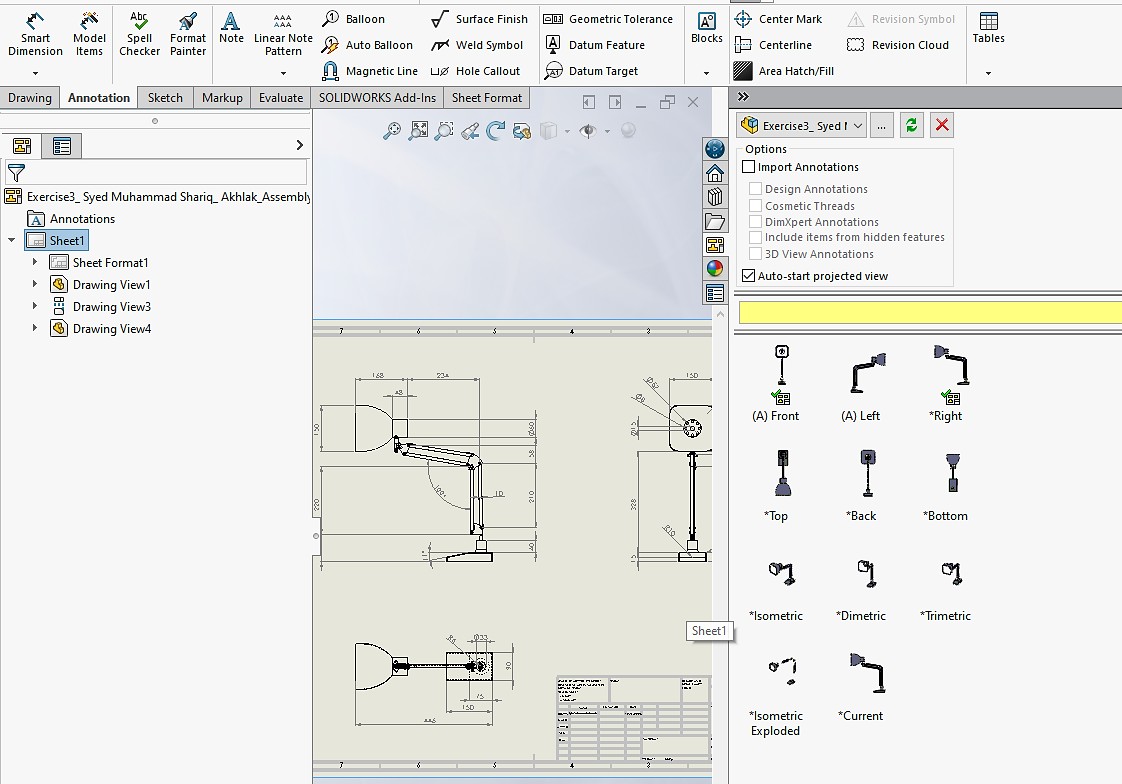
Insert the front, top, right, and isometric views first, then decide whether the part needs a section, detail, auxiliary, or broken-out view. The front view should show the strongest manufacturing identity of the part: the face a machinist would use to understand the main profile, hole pattern, or setup direction. If the first view is weak, every projected view becomes harder to read.
Adjust view scale and spacing before adding dimensions. This prevents crossed extension lines, cramped notes, and late sheet resizing. Avoid dimensioning to hidden lines unless necessary; a section or detail view usually explains internal geometry better. For mechatronic assemblies, the same discipline helps when matching supplier data, including downloadable component models from JLCMC's CAD file resources.
Import Model Dimensions, Then Clean Them Up
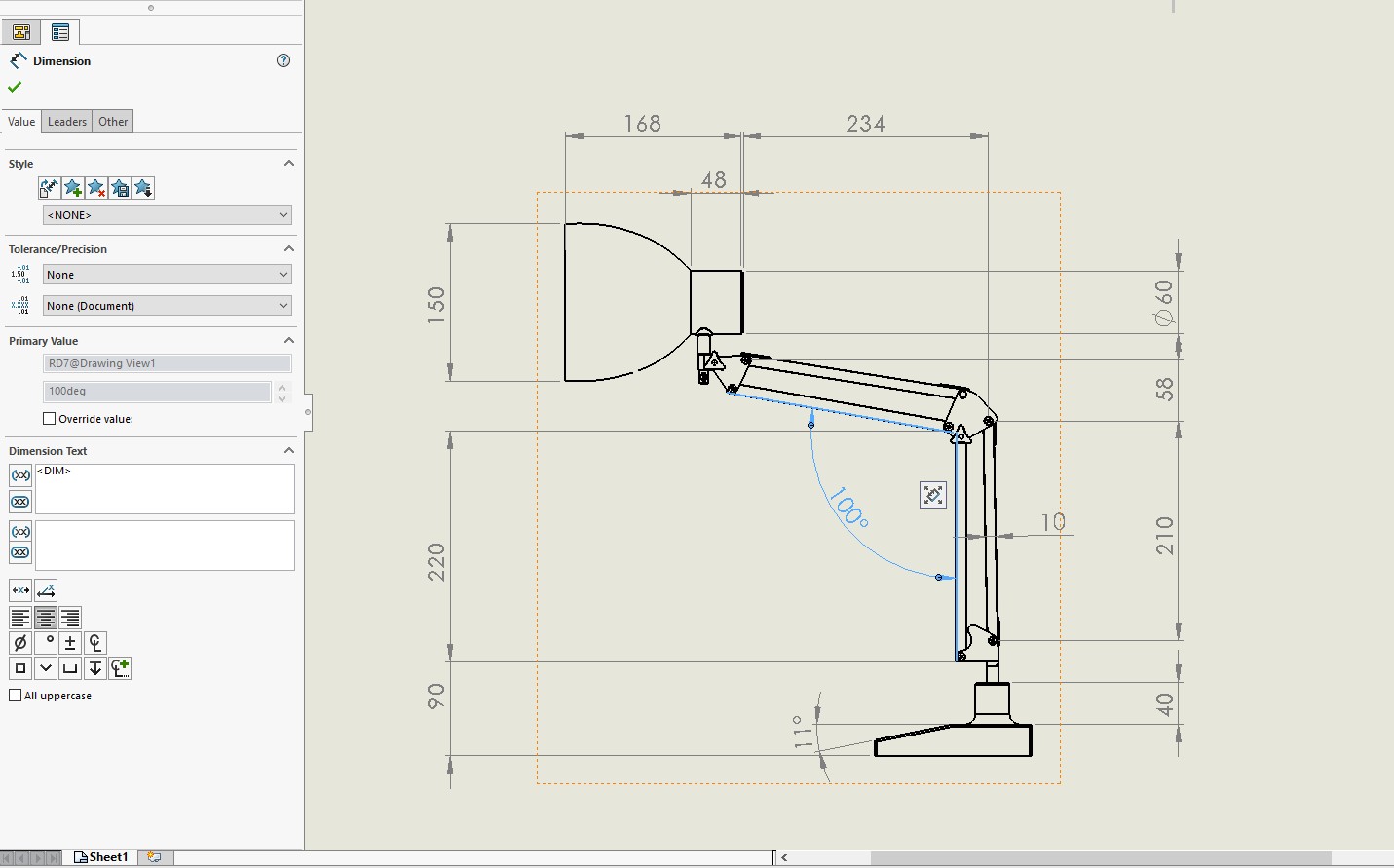
The Model Items command can import dimensions and annotations from model features into drawing views. This is useful when sketches and features were dimensioned with manufacturing intent from the beginning. SOLIDWORKS Help documents Model Items under Insert > Model Items, but the imported result still needs engineering cleanup.
Keep dimensions that define function, fit, location, and manufacturability; remove dimensions that only repeat obvious geometry or clutter the view. Add center marks, centerlines, hole callouts, surface finish notes, general tolerances, material specifications, heat treatment notes, and edge-break notes where the supplier needs them. If a dimension is attached to an edge likely to disappear after a fillet, pattern, or cut update, use a more stable reference.
SolidWorks Drawing Tutorial Checklist Before Export
Before export, run a manufacturing review rather than only a visual review. Check that the drawing has enough views, all critical dimensions are present, the tolerance scheme matches function, and no dangling dimensions remain after rebuild. Check the title block, revision, scale, units, material, finish, and quantity. Then export PDF for readable review and DWG or DXF only when editable 2D geometry is required.
For prototypes that may also be printed before machining, separate drawing requirements from print-file requirements. A 2D drawing controls inspected dimensions and notes; a print file controls mesh quality and build preparation. The JLC3DP CAD software guide is useful when the same SolidWorks design has to move toward additive manufacturing as well.
How Manual Drawing Creation Slows Engineers Down
Manual drawing work is still essential, but it does not scale gracefully when dozens of similar models need the same treatment. Most delays come from repeated setup and review load, not from one difficult command.
- Repetitive Setup Across Similar Parts: Rebuilding the same sheet format, view layout, scale decisions, and annotation pattern for plate-type or block-type parts adds little engineering value. The first drawing may feel quick, but the tenth exposes the cost. Tools like JLCCAN Auto-Drawing handle this category of repetitive drawing generation in a single command, but the output still needs review.
- Risk of Missed Annotations: Dense hole patterns, sections, and detail views make it easy to miss a center mark, chain dimension, or manufacturing note under deadline pressure. The problem compounds when several drawings are released together, because the reviewer must search for omissions across a batch.
- Revision Overhead After Heavy Edits: Parametric associativity helps, but it does not make every revision painless. If topology changes, features are removed, faces split, or edge references disappear, dimensions can become dangling and must be reapplied manually.
- Assembly Drawing Complexity: Assembly drawings add BOM linkage, balloon placement, exploded views, fastener clarity, and configuration control. In larger assemblies, balloon cleanup and view management can take longer than expected, especially when the BOM changes during review.
- Inconsistent Drawing Style Between Engineers: Two engineers can produce correct drawings that look different in spacing, note order, and dimension placement. That inconsistency slows review and supplier interpretation. A consistent first-pass layout makes the reviewer focus on engineering content instead of formatting.
- Low-Value Time Before Real Judgment Begins: The highest-value decisions involve tolerances, datum choices, manufacturing sequence, inspection method, and risk. Manual setup often consumes time before those decisions begin. JLCCAN is best understood in that space: it reduces first-pass generation effort for suitable parts, while engineers keep final control.
Automating SolidWorks 3D to 2D Drawing for Repetitive Workflows
Automation becomes useful when the SolidWorks 3D to 2D drawing task is repetitive, rule-based, and similar across many files. It is less useful when every part needs unusual views, custom tolerances, or manual interpretation. The correct question is whether the engineer should spend time generating the first layout again when the geometry pattern is already familiar.
What JLCCAN Auto-Drawing Does
JLCCAN Auto-Drawing is built for automated drawing creation inside repetitive SolidWorks workflows. Its core capabilities include: one-click drawing generation from parts or assemblies; smart main view detection that determines the most appropriate primary view and adjusts the view scale to fit the sheet; part-environment support for view generation plus full dimension and chain annotation; and assembly-environment support for standard 3-view generation only.
JLCCAN Auto-Drawing generates standard views and dimension chains straight from your SolidWorks parts, so you can spend your time on engineering review, not repetitive setup
Free Download >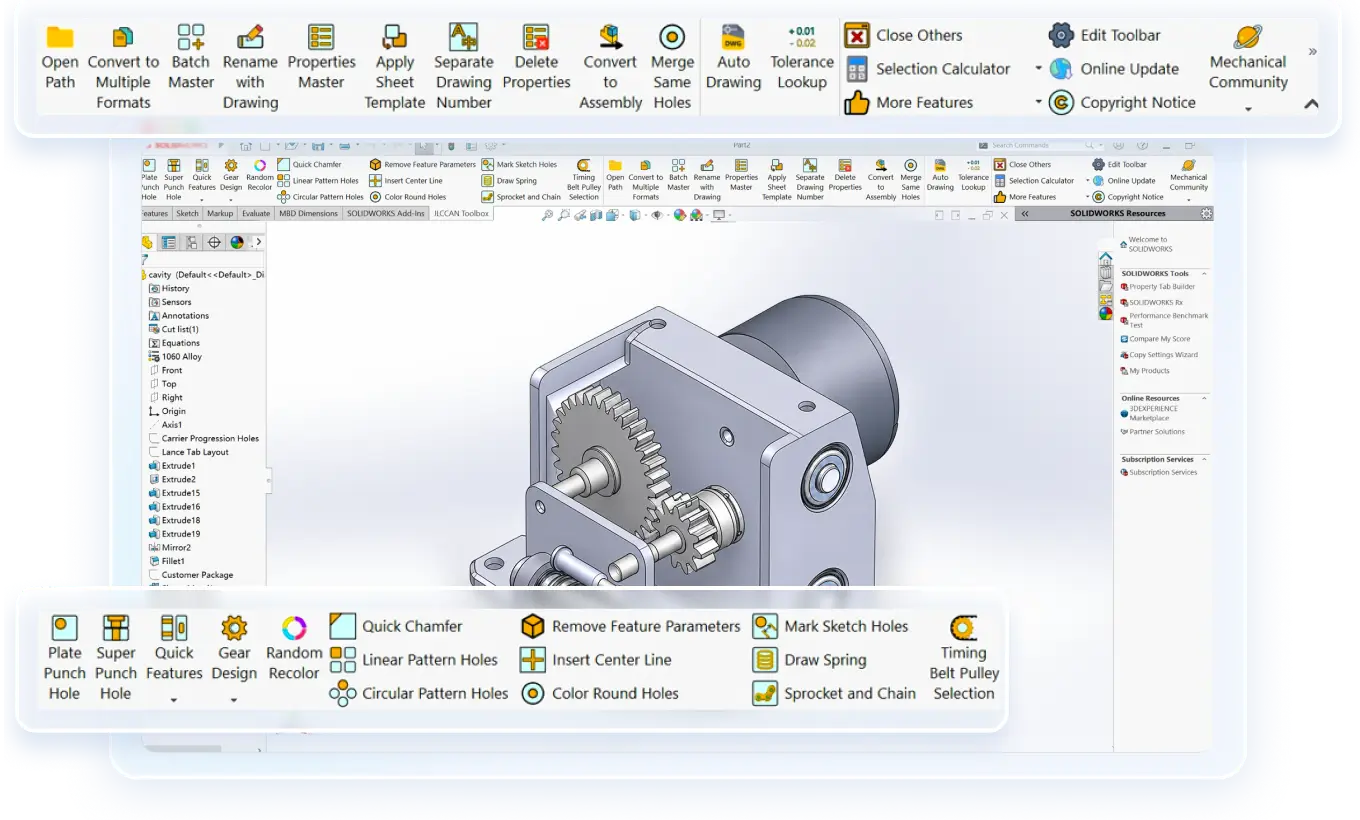
This part-versus-assembly distinction shapes how the tool fits into a workflow: it can carry a part drawing most of the way to completion, but on assemblies it only handles the initial view layout. Either way, generated drawings should be checked by an engineer before release, since automation can build the drawing structure but cannot decide functional tolerances, supplier notes, inspection priorities, or design risk.
When Auto-Drawing Works Best and When It Does Not
JLCCAN Auto-Drawing is best suited to plate-type and block-type parts, repetitive components with standard geometry, and teams that produce large drawing volumes. These are cases where view logic, sheet layout, and dimension patterns tend to repeat. A SolidWorks 3D to 2D drawing for a rectangular mounting plate, spacer block, or similar machined component is often a better automation candidate than a sculpted casting.
It is less suitable for shafts or axles, complex sheet metal, curved surfaces, irregular curve parts, flanges, complex geometry needing non-standard view placement, parts with specialized annotation or tolerance requirements, and one-off drawings where setup time is not the bottleneck. In those cases, manual control usually wins because the judgment load is higher than the setup load.
Manual vs Automated SolidWorks Drawing Workflows
Both manual and automated workflows can lead to accurate engineering drawings when they are reviewed properly. The difference is not that one method is serious and the other is casual. The difference is where the engineer spends time: direct layout creation in the manual route, or review and correction after automated first-pass generation.
Manual workflows remain better for highly customized parts, non-standard annotation schemes, or geometry that needs careful view interpretation. Automated workflows such as JLCCAN Auto-Drawing provide the strongest productivity benefit when drawing volume is high and the part family is predictable. The safest method is to let automation reduce repetitive setup, then let the engineer verify dimensions, tolerances, notes, and release quality.
| Manual Workflow | Automated Workflow | |
|---|---|---|
| Drawing Creation | Created individually from a blank or company template for each part. | Generated from a part or assembly with a single command. |
| View Generation | Engineer selects, places, and scales each view manually. | Primary view is auto-detected; standard views are placed automatically. |
| Dimensioning | Applied manually or imported through Model Items, then arranged by the engineer. | For parts, linear dimensions and dimension chains are generated from model geometry. |
| Setup Effort | Higher effort when many parts share similar drawing structure. | Lower first-pass setup effort for suitable repetitive parts. |
| Consistency | Can vary by engineer, especially under deadline pressure. | More consistent output structure across similar part types. |
| Revision Handling | Engineer controls corrections after model changes and dangling references. | Still requires engineering review after model changes. |
| Suitable Part Types | Any part type, including complex and one-off designs. | Best for plate-type, block-type, and repetitive standard-geometry parts. |
| Engineering Review | Required before release. | Required before release; automation supports generation, not approval. |
FAQs About SolidWorks 3D to 2D Drawing
Q: Can I Create a SolidWorks 3D to 2D Drawing Without Finishing the Model First?
You can start early, but it is usually inefficient to finalize the drawing before the model is stable. Early drawings are useful for design reviews, supplier questions, and packaging checks. Release drawings should wait until major features, hole locations, and interface faces are stable.
Q: What Views Are Usually Enough for a Simple Machined Part?
A simple prismatic part often needs front, top, right, and isometric views, plus a detail or section view if internal geometry is not clear. The correct number of views is the minimum required to remove ambiguity. Too many views can slow inspection because the reader has to decide which view controls the feature.
Q: Why Do Dimensions Turn Dangling in SolidWorks Drawings?
Dimensions usually become dangling when the model reference they were attached to no longer exists in the same form. This can happen after deleting a feature, splitting a face, changing a sketch, replacing a fillet, or altering hole geometry. To reduce rework, attach critical dimensions to stable references where possible.
Q: Should I Dimension Every Feature Visible on the Drawing?
No. A manufacturing drawing should define the part clearly, but redundant dimensions can create conflicts and inspection confusion. Use dimensions that control size, location, fit, function, and process needs. Add general tolerances and notes for repeated conditions instead of crowding every edge.
Q: Is Automated Drawing Generation Suitable for Assemblies?
It can help with first-pass assembly view creation when the requirement is a standard 3-view drawing. For assemblies, JLCCAN currently supports standard 3-view generation only. Automatic dimensioning and annotation are not supported. Assembly drawings still need manual attention for BOM structure, balloons, configurations, exploded states, and fit-related notes.
Q: Do Manufacturers Still Need 2D Drawings if I Send a STEP File?
Often, yes. A STEP file communicates geometry, but it may not fully communicate tolerances, surface finish, inspection requirements, material condition, heat treatment, revision notes, or critical-to-function features. For parts with fit, sealing, alignment, or safety requirements, a 2D drawing remains the control document.
Conclusion: Making a Drawing in SolidWorks
A SolidWorks 3D to 2D drawing remains a core engineering deliverable because manufacturing still needs controlled dimensions, tolerances, notes, and release information. Manual drawing creation is also a core skill, since it teaches engineers how to communicate design intent clearly. What changes at scale is how much of that repetitive setup an engineer has to do by hand. Tools like JLCCAN Auto-Drawing reduce this mechanical effort, but they don't remove the engineer from the loop. Every drawing, automated or not, still needs a final human review before it reaches the shop floor.
For teams evaluating where to draw that line, resources like JLCMC's product knowledge blog and JLC3DP's design tutorials are useful reading alongside SolidWorks' own drawing documentation, since manufacturability considerations often extend beyond the drawing itself.
Popular Articles
Keep Learning