SolidWorks Hole Wizard: How to Use It, Make Threaded Holes, and Show Them on the Drawing
14 min
- What the Hole Wizard Does
- How to Use the Hole Wizard
- Worked Example: Clearance and Tapped Holes in One Plate
- How Threaded Holes Work in the Model
- Showing Holes on the Drawing
- Why Your Thread or Callout Is Not Showing
- Where JLCCAN Fits
- Common Hole Wizard Mistakes
- FAQ
Quick answer: The Hole Wizard places standard holes (plain, counterbored, countersunk, tapped, slotted) from a library of sizes. Open it from the Features tab, choose the hole type and size on the Type tab, place the holes on the Positions tab, then show them on the drawing with Model Items, the Hole Callout tool or a hole table. For a tapped hole, remember the model shows the tap drill diameter and a cosmetic thread, not the full thread, and the drawing callout is what tells the shop the thread size.
A plain circle cut and a Hole Wizard hole look the same in the model. On the drawing they do not. One gives you a diameter. The other gives you "M6×1 TAP, 12 DEEP" or a counterbore note, written for you, and kept in step with the model when the size changes.
This guide covers when to use the Hole Wizard, how to place holes with it, how threaded holes really work, and how to show holes on the drawing with callouts or a hole table. It also covers why threads and callouts sometimes fail to appear, since that is where most of the time gets lost. For the surrounding workflow, see our guide to creating a SolidWorks 3D to 2D drawing.
Key Takeaways
- The Hole Wizard creates standard holes from a library, and each feature holds one hole type, so clearance holes and tapped holes are separate features.
- A tapped hole is modeled at the tap drill diameter with a cosmetic thread, and the callout on the drawing is what tells the shop the thread size.
- Hole callouts suit a few holes in one or two sizes, a hole table suits many holes in several sizes, and an Advanced Hole cannot be used for either.
- When a thread or callout does not appear, check the display settings first (Document Properties > Detailing > Display filter, with Display annotations selected), then the ISO behavior, where the callout has to be inserted by hand.
What the Hole Wizard Does
The Hole Wizard creates holes of standard types from a library of standards and sizes. The types you will use most:
| Hole type | Typical use | What the drawing shows |
|---|---|---|
| Hole (plain) | Clearance for a screw or pin | Diameter and depth, for example Ø6.6 THRU |
| Counterbore | Socket head screw sitting below the surface | Hole diameter, counterbore diameter and depth |
| Countersink | Flat head screw sitting flush | Hole diameter, countersink diameter and angle |
| Straight tap | Internal thread for a screw | Thread size, thread depth, and the tap drill if you show it |
| Tapered tap (pipe tap) | Pipe threads | Thread size and depth |
| Slot (plain, counterbore, countersink) | Adjustable mounting | Slot length, width and depth The Hole Wizard is not always needed. A single plain hole that does not match a standard size can be a simple extruded cut, and the cut is fine if you dimension it with Smart Dimension. The wizard pays off when you have several hole types, when threads are involved, or when you want the drawing callout to come from the model rather than from typing. The wizard also stores the hole's type and size in the FeatureManager tree, so the feature name tells you what the hole is without opening it. A caution about the neighbouring tool. SolidWorks also has an Advanced Hole feature for more complex holes. SolidWorks Help states that advanced holes cannot be selected for hole callouts or hole tables. If your drawing relies on either, use the Hole Wizard. |
How to Use the Hole Wizard
- Open it. Select the face you want to put holes on, then click Hole Wizard on the Features tab, or use Insert > Features > Hole > Wizard. You can also pick the face after you open the tool.
- Type tab: define the hole. Choose the hole type, the standard, the size and the end condition (blind depth, through all, up to next). Options vary by hole type. For tapped holes you also set thread depth and the cosmetic thread option.
- Positions tab: place the holes. Click to add sketch points on the face. They are ordinary sketch points, so you dimension them and add relations like any other sketch. Do not sketch circles here; the Type tab sets the diameter.
- Finish. Click OK. The feature appears in the tree with its type and size in the name.
- Change it later. Edit Feature to change the size or depth, and the hole updates everywhere that reads it, including drawing callouts.
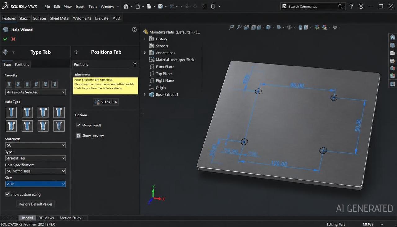
- Two points that save time.
- Each Hole Wizard feature has one hole type. SolidWorks Help says to add different hole types as separate features. Use one feature for six identical holes, not six features for the same hole, and a second feature for the tapped ones.
- A Hole Wizard feature contains two sketches. One is the position sketch and the other is the hole profile. The position sketch is where your hole locations live, so dimension it from the datums the part actually uses (see our post on SolidWorks dimensioning).
- If you use a hole size often, save it as a favorite from the Hole Wizard so it is one click next time.
Worked Example: Clearance and Tapped Holes in One Plate
Take the 120 × 80 × 10 mm plate from our dimensioning guide. It needs four clearance holes for M6 screws and two M6 tapped holes for a mating bracket.
| Holes | Hole Wizard feature | Settings | Drawing callout should read |
|---|---|---|---|
| 4 corner holes | Feature 1: Hole | ISO, M6 clearance (medium), through all | 4× Ø6.6 THRU |
| 2 mounting holes | Feature 2: Straight tap | ISO, M6×1, blind 12 mm thread depth, cosmetic thread on | 2× M6×1 ↓ 12 (thread depth) Two features, because the hole types differ. Both use position sketches dimensioned from the left and bottom edges, the same datums the plate locates on. The tapped holes need an extra look. The model does not show an M6 hole. It shows a hole at the tap drill diameter, which for an M6×1 thread is 5.0 mm, with a cosmetic thread around it. That is correct. The tapped hole is a hole the machinist drills at 5.0 mm and then taps. The callout on the drawing is what says M6. |
How Threaded Holes Work in the Model
SolidWorks represents threads with a cosmetic thread, which is an annotation, not geometry. SolidWorks Help describes it as the major diameter on a hole (or the minor diameter on a boss). For a tapped hole with a cosmetic thread made in the Hole Wizard, the hole diameter is the tap drill diameter. Without a cosmetic thread, the hole is cut at the outer diameter of the thread.
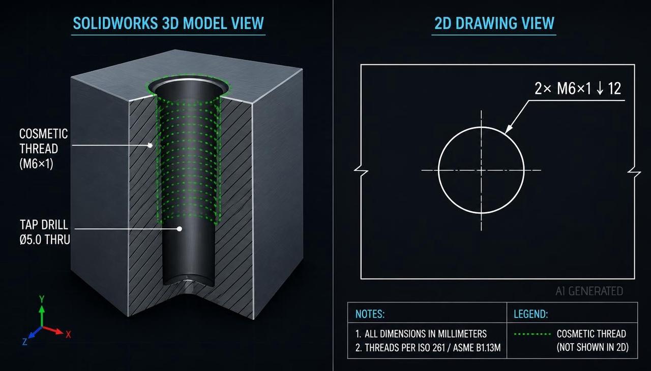
The Hole Wizard gives you three choices for how to treat the thread.
| Option | What the model gets | When to use it |
|---|---|---|
| Tap drill diameter | A hole at the tap drill diameter, no thread annotation | Rare. You want the drilled hole and nothing else |
| Cosmetic thread (with thread callout) | A hole at tap drill diameter, a cosmetic thread, and a thread callout | The normal choice for drawings |
| Remove thread | A hole at the thread's outer diameter | Interference checks or models for hardware where the nominal diameter is what you need For most manufacturing drawings the cosmetic thread is the right option. Modeling a real helical thread is slow, makes the file heavy, and rarely helps the machinist, who reads the callout. If the part is going to a shop, send the drawing together with a clean model, as our JLCCNC colleagues describe in their guide to preparing CAD files for CNC machining. A frequent mix-up is thread depth against hole depth. A tapped hole is deeper than its thread, because the drill must go past the thread so the tap does not bottom out. If your drawing says "12 deep" and does not say which depth it means, the shop has to guess. Put both in the callout when it matters. |
Showing Holes on the Drawing
There are three ways, and each suits a different case.
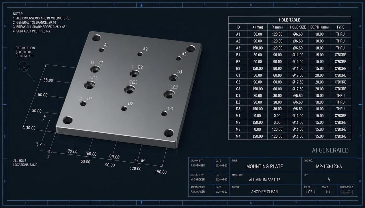
Model Items
Model Items can pull hole callouts for Hole Wizard holes into the drawing views automatically. This is the quickest route and usually the first step.
Hole Callout
The Hole Callout tool (Annotation tab) adds a single callout to a hole you pick, and it reads the hole's type, size and depth from the feature. If you pick one of several identical holes, SolidWorks counts the instances and writes the multiplier. You can edit the callout text, and the format follows your document settings.
Hole table
A hole table lists every hole with a tag and its position. Use Insert > Tables > Hole Table, then pick a vertex as the origin. SolidWorks measures each hole from that origin and tags the hole with a letter or number. The default templates give TAG, XLOC, YLOC and SIZE columns, and combined templates merge holes of the same size. Tags can be alphabetic, where the letter marks the size and the number marks the instance, or numeric. Positions can be ordered by XY or, for turned parts, radially. One table can cover several views, with one datum per view.
The origin you pick works like the zero in ordinate dimensioning: it should be the datum the part locates on, not a convenient corner (more on this in our dimensioning guide).
Callouts or a table?
| Situation | Better choice | Why |
|---|---|---|
| A few holes, one or two sizes | Hole callouts and normal dimensions | Reader sees size and position beside each hole |
| Many holes in several sizes | Hole table | One origin, no forest of dimension lines |
| Hole pattern on a plate that mates with another | Callout for size, positions dimensioned from datums | Spacing tolerance stays visible (see the chain and baseline example) |
| Turned part with holes around the axis | Hole table with radial ordering | Positions are angular, not XY |
| Slots and non-circular holes | Table, but enter the size yourself | SolidWorks lists the centre coordinates only, not the size A hole table does not remove the need for tolerance. Positions in the table still need a tolerance, which usually comes from the general tolerance block or a note. |
Why Your Thread or Callout Is Not Showing
Most cases come down to a short checklist.
| Symptom | What to check |
|---|---|
| Cosmetic thread missing in the part | Was the cosmetic thread option selected in the Hole Wizard feature? Is annotation display turned on (View > Hide/Show > Annotations)? |
| Thread shows in the part but not the drawing | In Document Properties > Detailing, check that Cosmetic threads and Shaded cosmetic threads are selected under Display filter, and that Display annotations is selected |
| Thread shows in the part but not the assembly | Check the assembly's own annotation visibility, and whether the hole was created at part or assembly level |
| Thread callout missing from an ISO drawing | Help says callouts are inserted automatically only in ANSI drawings. In ISO and some other standards, right-click the cosmetic thread and choose Insert Callout |
| Hole not selectable for a callout | It may be an Advanced Hole, which cannot be used for callouts or tables |
| Hole missing from the hole table | Holes that intersect another face are left out, because the geometry is interrupted |
| Wrong hole size on the drawing | Check whether the hole was made as a plain cut. Cuts have no Hole Wizard data to read One easy habit prevents most of these. Under Display filter in Document Properties > Detailing, select Cosmetic threads and Shaded cosmetic threads in your templates, and keep Display annotations selected, so every new part and drawing starts with them visible. |
Where JLCCAN Fits
Hole work is where a plugin saves repeated clicks. JLCCAN's features page lists several hole-related tools:
- Auto Hole Generation creates counterbore holes, tapped holes, locating pin holes and pattern holes, with automatic centerlines and placement across multiple faces.
- Mating Hole Check checks hole alignment, specification matching and interference between mating parts before assembly.
- Auto Assemble Screws identifies hole features and inserts screws, washers and nuts with mates in bulk.
- Quick Features includes holes on cylindrical faces and conversion of third-party hole features.
- Auto Drawing & Dimensioning can apply hole tables to drawings, along with dimensions and annotations in batch.
- The point that matters most for the drawing is that holes made with Auto Hole Generation are standard Hole Wizard features. The Hole Callout tool and hole tables read them like any other Hole Wizard hole, so the callouts in this guide work on them unchanged. The hole standard Auto Hole Generation supports is GB, so if your drawings follow ANSI or ISO, check the generated hole sizes against your own standard before you release the drawing.
- The sequence in this guide is the same with or without a plugin: choose the hole type, place the holes from the right datums, then show them on the drawing in the way the shop expects. A tool changes how fast you place them. It does not decide whether a hole should be clearance or tapped, or which face the table's origin sits on.
JLCCAN Auto-Drawing generates standard views and dimension chains straight from your SolidWorks parts, so you can spend your time on engineering review, not repetitive setup
Free Download >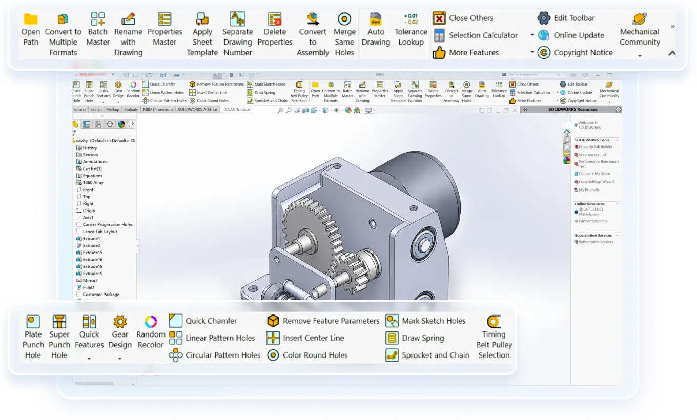
Common Hole Wizard Mistakes
- Using the major diameter for a tapped hole. A hole drilled at 6.0 mm for an M6 thread is not a tapped hole. Pick Straight Tap and the model applies the tap drill diameter.
- Mixing hole types in one feature. The Hole Wizard takes one type per feature. Split them.
- Drawing the hole circle on the Positions tab. Place points, not circles. The Type tab sets the size.
- Relying on Advanced Hole for drawing callouts. It is not supported for callouts or hole tables.
- Leaving annotations hidden. The most common reason a thread "disappears" is a display setting, not a modeling error.
- Specifying depth without saying which depth. For tapped holes, state the thread depth and the drill depth when they differ.
- Choosing a hole table origin because it is easy to click. The origin should be the datum. A table measured from the wrong corner is accurate and useless.
FAQ
Where is the Hole Wizard in SolidWorks? On the Features tab of the CommandManager, or under Insert > Features > Hole > Wizard. The tool opens a PropertyManager with a Type tab and a Positions tab.
How do I make a threaded hole in SolidWorks? Open the Hole Wizard, choose Straight Tap, select the standard and thread size, set the thread depth, and turn on the cosmetic thread option. The model shows a hole at the tap drill diameter with a cosmetic thread, and the drawing callout carries the thread size.
What is the difference between a tapped hole and a clearance hole? A tapped hole has an internal thread and receives a screw directly. A clearance hole is larger than the screw and lets it pass through. In the Hole Wizard, tapped holes use the Straight Tap or Tapered Tap types, and clearance holes use the plain Hole type with a fit class.
How do I add a custom size or thread to the Hole Wizard? For a one-off size, use the Show Custom Sizing option, which lets you enter your own values. For a size you will reuse, save it as a favorite. Adding new standard threads to the Hole Wizard library depends on your version and is usually handled by an administrator.
Why does the hole callout not show the thread? Usually the cosmetic thread option was not selected in the hole, annotations are hidden, or the drawing standard is ISO and the callout was not inserted automatically. Right-click the cosmetic thread and choose Insert Callout to show it.
Hole Wizard or a plain cut: which should I use? Use the Hole Wizard for standard holes, threads, counterbores and countersinks, and when you want callouts that follow the model. A plain cut is fine for a single non-standard opening that you will dimension by hand.
Popular Articles
Keep Learning
Engineering Drawing Examples: Annotated Part, Assembly, Exploded, Weldment and Sheet Metal Drawings
Quick answer: A good engineering drawing example shows more than the views. It shows how the views, dimensions, symbols, notes and title block work together for one specific part. The six examples below cover a machined part, a part with an inclined face, an assembly, an exploded assembly, a welded frame and a sheet metal part, and each one says why it is drawn the way it is. Use them as a pattern for your own drawings, or as exercises. Searching for engineering drawing examples mostly returns picture......
How to Export a SolidWorks Drawing to PDF, DXF and DWG (and Export Many at Once)
Quick answer: To export a SolidWorks drawing to PDF, use File > Save As, choose PDF as the type and set the options for colour, fonts and quality. For DXF or DWG, use File > Export As in newer versions (File > Save As in older ones), choose the type and set the export options, including whether a multi-sheet drawing goes to paper space. Most export problems come from the drawing's display quality, scale and fonts, not from the file type. The drawing is finished and checked, and now someone needs it in......
SolidWorks Weldment Drawing: Views, Cut List, Balloons, and Weld Symbols
Quick answer: A SolidWorks weldment drawing shows a welded frame in a few views of the whole weldment, a cut list that lists each structural member with its length and quantity, balloons tied to that list, and weld symbols that say how each joint is made. Build the views and the Weldment Cut List table from the weldment part, add balloons so their numbers follow the cut list, and bring in or add weld symbols last. The drawing is only as good as the cut list in the part, so check the properties and the......
Drawing Views in SolidWorks: Orthographic, Isometric, Section, Auxiliary, Detail, and Break Views
Quick answer: Drawing views are 2D pictures of a 3D model. Orthographic views (front, top, right) show true shapes and carry the dimensions, an isometric view shows the part's general form, and derived views handle special jobs: section views for the inside, auxiliary views for inclined faces, detail views for small features, and break and crop views for long or crowded views. In SolidWorks, you place a base view first and derive the others from it, which keeps them aligned and linked to their parent.......
SolidWorks Exploded View: Create It, Add Explode Lines, and Show It on a Drawing
Quick answer: An exploded view is built in the assembly, not in the drawing. Click Exploded View, add steps that move components along an axis, add explode lines with Explode Line Sketch, then on the drawing select a model view of the assembly and turn on Show in exploded or model break state. Balloons on that view read from the BOM as usual, and most missing explode lines come down to sketch display or the wrong configuration. The shop gets twelve part drawings and a pile of parts. Nothing says which......
Assembly Drawing vs Detail Drawing in SolidWorks: What Goes on Each, and How to Build the Assembly Drawing
Quick answer: An assembly drawing shows how the parts of a product fit together, with views, a bill of materials and balloons that link each part to its row. A detail drawing shows one part with everything needed to make it. In SolidWorks, you build the assembly drawing from the assembly, add a section view where it helps, insert the BOM and balloons, and add an exploded view when the reader needs the order of assembly (see our exploded view guide). The shop gets twelve part drawings and a pile of par......