Assembly Drawing vs Detail Drawing in SolidWorks: What Goes on Each, and How to Build the Assembly Drawing
8 min
- Assembly Drawing, Detail Drawing and Exploded View
- What Goes on an Assembly Drawing
- Build the Assembly Drawing in SolidWorks
- Example: The Mounting Assembly
- Fixing the Usual Problems
- Where JLCCAN Fits
- Common Assembly Drawing Mistakes
- FAQ
Quick answer: An assembly drawing shows how the parts of a product fit together, with views, a bill of materials and balloons that link each part to its row. A detail drawing shows one part with everything needed to make it. In SolidWorks, you build the assembly drawing from the assembly, add a section view where it helps, insert the BOM and balloons, and add an exploded view when the reader needs the order of assembly (see our exploded view guide).
The shop gets twelve part drawings and a pile of parts. Nothing says which screw goes where, in what order, or how the clamp fits on the bracket. The part drawings were right, and the one that explains how they fit together was missing.
This guide explains what assembly drawings and detail drawings are and what goes on each, then shows how to build an assembly drawing in SolidWorks and keep balloons and the BOM in step. The exploded view, which shows the order of assembly, has its own guide. For the basic workflow of making any drawing, see our guide to creating a SolidWorks 3D to 2D drawing.
Key Takeaways
- A detail drawing describes one part for manufacture, an assembly drawing shows how parts fit together, and an exploded drawing is a third type with its own purpose.
- Section Scope excludes parts such as screws, pins and shafts from a cut, which follows drawing convention for those parts.
- Selecting Auto hatching in Section Scope makes neighbouring cut faces alternate their hatch angle, so adjacent parts can be told apart.
- Balloons tied to the BOM keep item numbers correct when the assembly changes, while a typed note does not.
Assembly Drawing, Detail Drawing and Exploded View
These three are often confused. They answer different questions.
| Detail drawing (part drawing) | Assembly drawing | Exploded assembly drawing | |
|---|---|---|---|
| Question it answers | How is this part made and inspected? | How do these parts fit together? | In what order and where does each part go? |
| Shows | One part, full dimensions and tolerances, material, finish | Several parts in position, overall size, interface dimensions | Parts separated along their assembly axes, with lines to their positions |
| Typical content | Views, dimensions, tolerances, notes, title block | Views, sections, BOM, balloons, notes | Pictorial view, balloons, BOM |
| Read by | Machinist, inspector | Assembler, buyer, service | Assembler, service, customer Standards such as ASME Y14.24 describe the types and applications of engineering drawings, and the names differ between companies (top assembly, general assembly, sub-assembly drawing). The structure is the same: a top assembly shows the whole product, a sub-assembly drawing shows one unit within it, and detail drawings show the individual parts. |
What Goes on an Assembly Drawing
An assembly drawing is not a pile of detail dimensions. It carries what the reader needs to put things together and order them.
- Views that show how parts relate. Usually orthographic views plus an isometric, and sections where internal fit matters.
- Bill of materials listing every part with item number, part number, description and quantity (see our [BOM guide, LINK: add when published]).
- Balloons linking each part in the views to its BOM row.
- Overall dimensions and the dimensions that matter at the interfaces: mounting positions, fits, clearances, gaps. Part dimensions stay on the detail drawings.
- Reference dimensions for sanity checks, kept to a minimum.
- Assembly notes: torque values, adhesive, lubrication, order of assembly, alignment marks.
- Title block with the assembly number and revision.
- The usual mistake is to dimension every feature on the assembly drawing. It duplicates the detail drawings, and the two sets drift apart, which breaks the rule of dimensioning each feature once (see our SolidWorks dimensioning). A welded frame is a special case, because it lists its members in a cut list instead of a BOM; see our weldment drawing guide.
Build the Assembly Drawing in SolidWorks
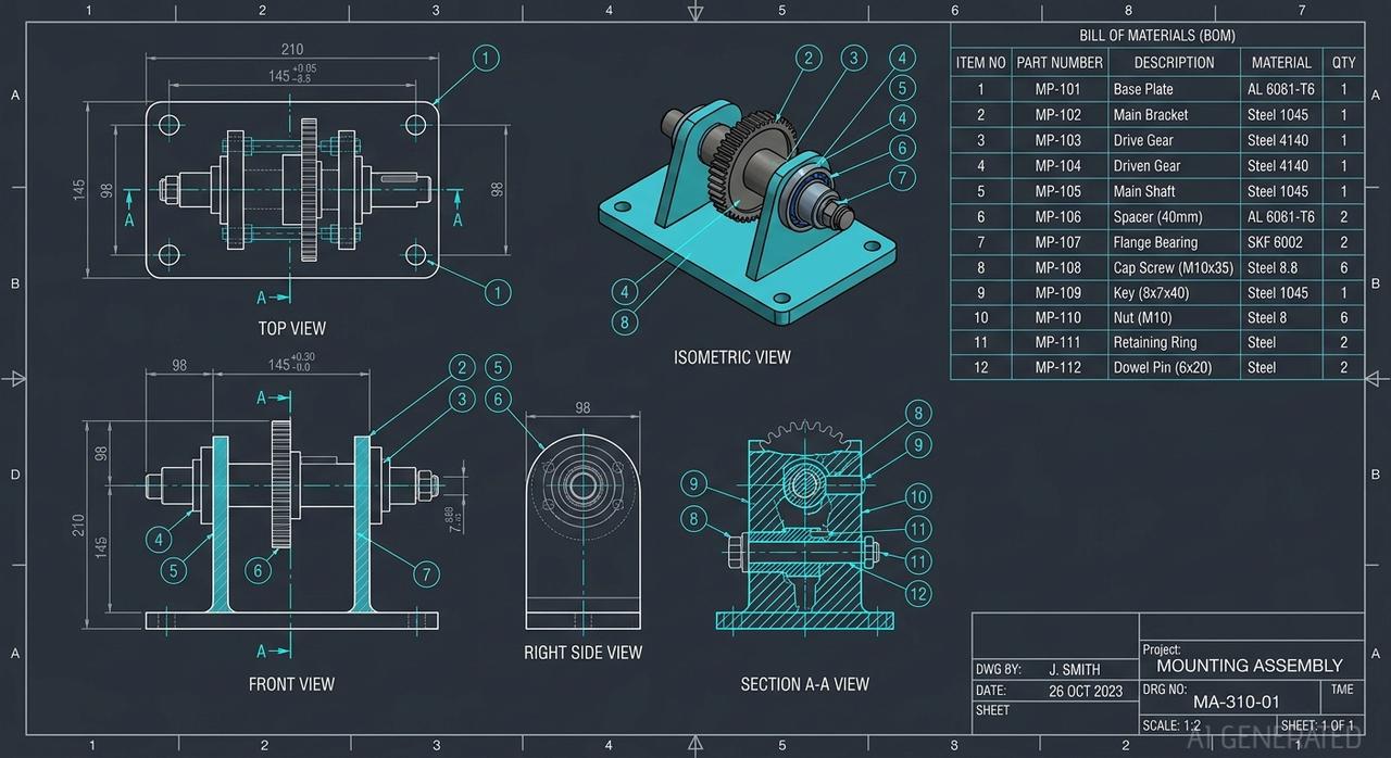
Start from the assembly and use Make Drawing from Assembly, as in our drawing guide. Then:
- Place the views. Front, top and right, plus an isometric. Choose the sheet size from the largest view, and leave space for the BOM.
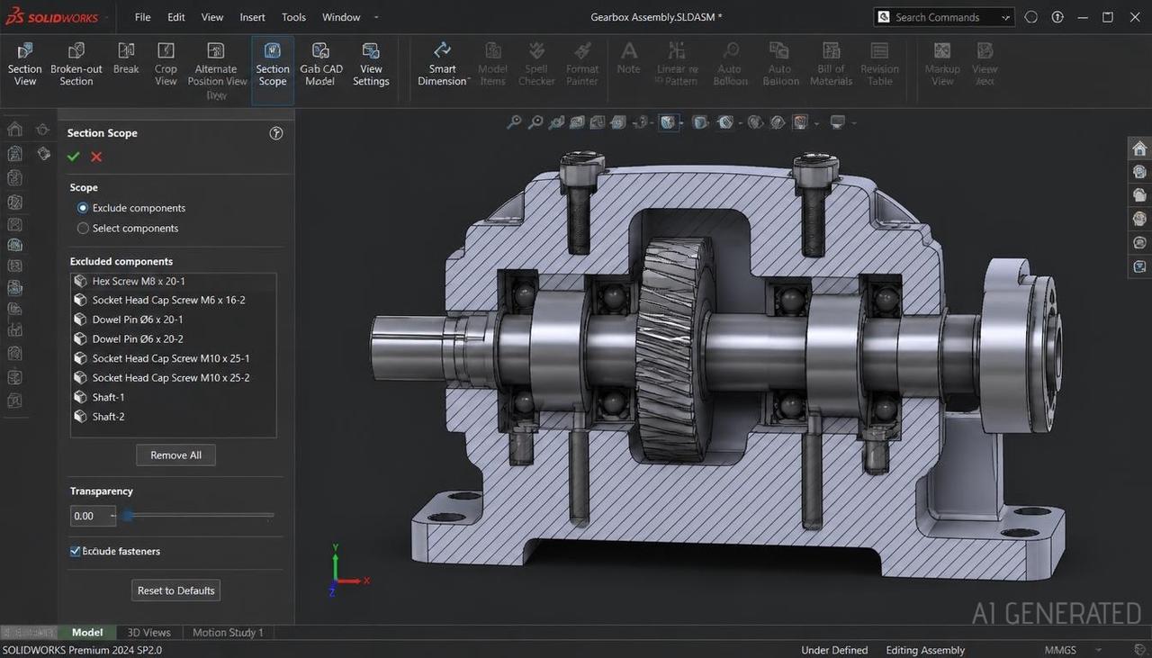
- Add a section where fit matters. In an assembly section, components are cut and hatched. Use Section Scope in the Section View PropertyManager to exclude components that should not be cut, such as screws, pins and shafts, which are drawn whole by convention. Selecting Auto hatching in Section Scope makes neighbouring cut faces alternate their hatch angle, so adjacent parts can be told apart.
- Insert the BOM. Use Insert > Tables > Bill of Materials, pick the template and the BOM type. For the balloon numbers to match what a reader expects, decide on the type first: Top-level only for a drawing where sub-assemblies have their own drawings, Parts only or Indented where one sheet must show everything.
- Add balloons. Auto Balloon places balloons on the components in a view, and their numbers follow the BOM. Components set to Exclude from bill of materials show an asterisk instead of a number.
- Dimension the interfaces. Overall size, mounting dimensions, gaps, and any fit called out by the design.
- Add assembly notes and check the title block fields.
- For a large assembly, keep sheet 1 for the orthographic views and put the exploded view on its own sheet, as described in our exploded view guide. The orthographic sheet is for fit and size, and the exploded sheet is for order and parts.
Example: The Mounting Assembly
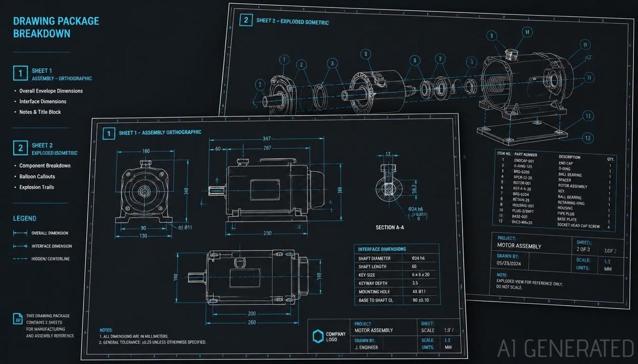
Here is a plan for the mounting assembly used in our BOM guide: base plate, bracket, clamp sub-assembly (clamp arm and two M5 screws), four M6 screws with washers, and two dowel pins. The drawing set is planned like this:
| Sheet | Contents |
|---|---|
| 1 | Front, top and right views, one section through the dowel pins, overall and mounting dimensions, notes |
| 2 | Isometric exploded view with balloons and the BOM (Parts only, so loose parts all have a number), made as described in the exploded view guide |
| 3 and later | Detail drawings of the plate, the bracket and the clamp arm Sheet 1 answers fit and size, sheet 2 answers order and parts, and the later sheets answer how each part is made. |
Fixing the Usual Problems
| Symptom | Likely cause | Fix |
|---|---|---|
| Balloons show asterisks | Components excluded from the BOM | Clear the exclusion, or leave the balloon off |
| Section hatch crosses a screw | The screw was cut | Exclude it with Section Scope |
| Balloon numbers do not match the BOM | View linked to another table | Link balloon text to the right BOM For problems specific to exploded views, such as missing explode lines or a missing exploded state, see the exploded view guide. |
Where JLCCAN Fits
Assemblies are where small repetitive jobs add up: placing screws, checking holes, keeping the BOM tidy. JLCCAN's features page lists several tools that sit before the drawing. Auto Assemble Screws identifies hole features and inserts screws, washers and nuts with mates in bulk. Mating Hole Check validates hole alignment and specification matching between mating parts. Advanced BOM manages assembly BOM structures and exports to Excel.
For the drawing itself, the existing guide on our blog states the limit: for assemblies, Auto-Drawing generates standard three views only and does not add automatic dimensioning or annotation, so assembly drawings still need manual work for the BOM, balloons and configurations.
The practical order is the same with or without a plugin: build the assembly correctly (fasteners placed, holes aligned, properties filled), then the exploded view if you need one, then the drawing.
JLCCAN Auto-Drawing generates standard views and dimension chains straight from your SolidWorks parts, so you can spend your time on engineering review, not repetitive setup
Free Download >
Common Assembly Drawing Mistakes
- Dimensioning every part on the assembly drawing. Those dimensions belong on the detail drawings.
- Cutting fasteners in a section. Use Section Scope so they are drawn whole.
- Choosing the BOM type after placing balloons. SolidWorks Help warns that changing the type of an existing BOM increases file size and may slow performance, so decide the type first. If it has to change, delete the table and insert a new one (see our BOM guide).
- Mixing views and BOM on a crowded sheet. Put the exploded view on its own sheet.
- Skipping the assembly notes. Torque and order of assembly are the information most often missing.
FAQ
What is an assembly drawing? A drawing that shows how the parts of a product fit together, with views, a BOM and balloons that link parts to their rows. It also has overall and interface dimensions and assembly notes, and leaves part dimensions to the detail drawings.
What is the difference between an assembly drawing and a detail drawing? A detail drawing describes a single part in full so it can be made and inspected. An assembly drawing describes how several parts go together.
What is a general assembly drawing? The drawing of the top-level product, showing the whole assembly with its overall size and how the sub-assemblies and parts fit. Sub-assembly drawings then cover each unit inside it, and detail drawings cover each part. Company naming varies, so check your own standard.
What is a part drawing? Another name for a detail drawing: one part with the dimensions, tolerances, material and finish needed to make and inspect it.
Popular Articles
Keep Learning
Engineering Drawing Examples: Annotated Part, Assembly, Exploded, Weldment and Sheet Metal Drawings
Quick answer: A good engineering drawing example shows more than the views. It shows how the views, dimensions, symbols, notes and title block work together for one specific part. The six examples below cover a machined part, a part with an inclined face, an assembly, an exploded assembly, a welded frame and a sheet metal part, and each one says why it is drawn the way it is. Use them as a pattern for your own drawings, or as exercises. Searching for engineering drawing examples mostly returns picture......
How to Export a SolidWorks Drawing to PDF, DXF and DWG (and Export Many at Once)
Quick answer: To export a SolidWorks drawing to PDF, use File > Save As, choose PDF as the type and set the options for colour, fonts and quality. For DXF or DWG, use File > Export As in newer versions (File > Save As in older ones), choose the type and set the export options, including whether a multi-sheet drawing goes to paper space. Most export problems come from the drawing's display quality, scale and fonts, not from the file type. The drawing is finished and checked, and now someone needs it in......
SolidWorks Weldment Drawing: Views, Cut List, Balloons, and Weld Symbols
Quick answer: A SolidWorks weldment drawing shows a welded frame in a few views of the whole weldment, a cut list that lists each structural member with its length and quantity, balloons tied to that list, and weld symbols that say how each joint is made. Build the views and the Weldment Cut List table from the weldment part, add balloons so their numbers follow the cut list, and bring in or add weld symbols last. The drawing is only as good as the cut list in the part, so check the properties and the......
Drawing Views in SolidWorks: Orthographic, Isometric, Section, Auxiliary, Detail, and Break Views
Quick answer: Drawing views are 2D pictures of a 3D model. Orthographic views (front, top, right) show true shapes and carry the dimensions, an isometric view shows the part's general form, and derived views handle special jobs: section views for the inside, auxiliary views for inclined faces, detail views for small features, and break and crop views for long or crowded views. In SolidWorks, you place a base view first and derive the others from it, which keeps them aligned and linked to their parent.......
SolidWorks Exploded View: Create It, Add Explode Lines, and Show It on a Drawing
Quick answer: An exploded view is built in the assembly, not in the drawing. Click Exploded View, add steps that move components along an axis, add explode lines with Explode Line Sketch, then on the drawing select a model view of the assembly and turn on Show in exploded or model break state. Balloons on that view read from the BOM as usual, and most missing explode lines come down to sketch display or the wrong configuration. The shop gets twelve part drawings and a pile of parts. Nothing says which......
Assembly Drawing vs Detail Drawing in SolidWorks: What Goes on Each, and How to Build the Assembly Drawing
Quick answer: An assembly drawing shows how the parts of a product fit together, with views, a bill of materials and balloons that link each part to its row. A detail drawing shows one part with everything needed to make it. In SolidWorks, you build the assembly drawing from the assembly, add a section view where it helps, insert the BOM and balloons, and add an exploded view when the reader needs the order of assembly (see our exploded view guide). The shop gets twelve part drawings and a pile of par......