How to Export a SolidWorks Drawing to PDF, DXF and DWG (and Export Many at Once)
12 min
- Which Format for Which Job
- Export a Drawing to PDF
- Print to Scale and Actual Size
- Export a Drawing to DXF or DWG
- DXF From a Part, Sketch or Assembly
- Export Many Drawings at Once
- Fixing the Usual Export Problems
- Where JLCCAN Fits
- Common Export Mistakes
- FAQ
Quick answer: To export a SolidWorks drawing to PDF, use File > Save As, choose PDF as the type and set the options for colour, fonts and quality. For DXF or DWG, use File > Export As in newer versions (File > Save As in older ones), choose the type and set the export options, including whether a multi-sheet drawing goes to paper space. Most export problems come from the drawing's display quality, scale and fonts, not from the file type.
The drawing is finished and checked, and now someone needs it in a format SolidWorks does not use. Purchasing wants a PDF. The laser shop wants a DXF. A customer wants a DWG for their own CAD. Each of these is a File menu away, and each has two or three settings that decide whether the result is usable or only looks right on your screen.
This guide covers which format suits which job, how to export a drawing to PDF, how to export it to DXF or DWG, how to get DXF from a part, sketch or assembly, how to export many drawings at once, and how to fix the faults people meet most.
Key Takeaways
- The format follows the use: PDF for review and release, DXF or DWG for CAM and laser cutting.
- Save As PDF is generated by SolidWorks and rebuilds the drawing first, while Print to PDF hands the job to a third-party printer driver.
- For laser cutting, export a face, a sketch or the flat pattern and check the file in a viewer, because saving a whole part as DXF brings in all of its geometry.
- Folders of drawings can be exported with Task Scheduler's Export Files task (SOLIDWORKS Professional or higher) or with JLCCAN Batch Manager, which converts to PDF, DXF and DWG and rebuilds each drawing first.
Which Format for Which Job
| Format | Use it to | Keep in mind |
|---|---|---|
| Send a drawing for reading, approval or printing | It is a picture of the sheet, so it cannot be edited as CAD. Fonts and DPI decide how it looks | |
| DXF | Hand 2D geometry to another CAD package, a laser cutter or a CNC programmer | Scale, layers and view quality decide whether the geometry is usable |
| DWG | Hand 2D geometry to someone working in AutoCAD-based software | Same settings as DXF, and the same checks If the reader only needs to look at the drawing, send a PDF. If the reader needs to measure it, cut from it or edit it, send DXF or DWG, and check the result by opening it in a viewer before you send it. |
Export a Drawing to PDF
SolidWorks Help describes the route in a few steps. Open the drawing, click File > Save As, and in Save as type choose Adobe Portable Document Format (*.pdf). Click Options to set the PDF export options, then click OK, type a file name and save. These steps are from the 2025 edition of SolidWorks Help.
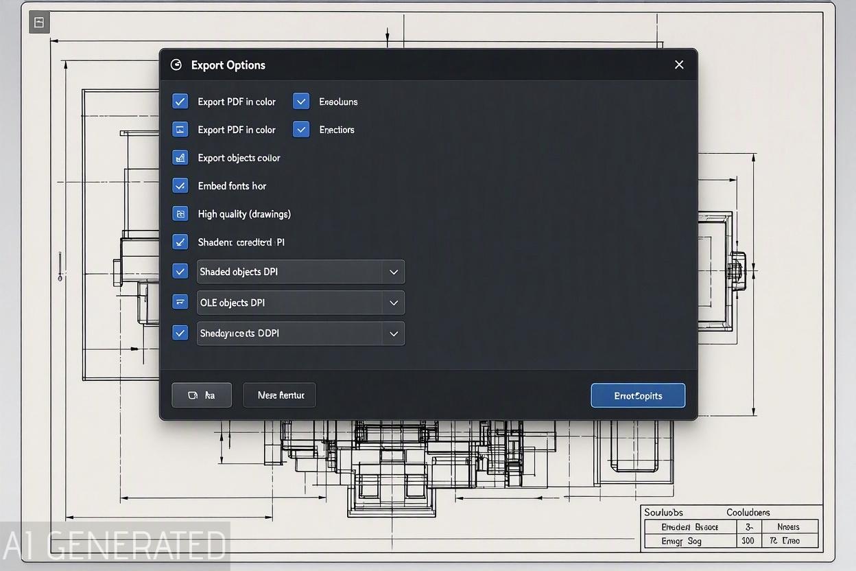
The options decide the quality of the result.
| Option | What it does |
|---|---|
| Export PDF in color | Keeps colour. It increases the file size and the time to save |
| Embed fonts | Puts the fonts in the PDF so it looks the same on any computer |
| High quality (drawings) | Saves the drawing at higher quality |
| DPI for shaded and draft geometry (drawings) | Higher values give a sharper image, a bigger file and a slower save |
| DPI for OLE objects (drawings) | The same, for embedded objects such as Excel tables |
| Include layers set not to print | Puts layers that would not normally print into the PDF |
| Include bookmarks | Adds bookmarks to the PDF |
| Use header and footer from File > Print | Adds the print header and footer |
| Use printer line weights | Uses the default printer line weights Two limits are worth knowing. For drawings, SolidWorks Help says the PDF format is limited to a sheet size of 200 inches (508 cm) in width and height. And if the drawing has non-English characters, the fonts that draw them must be available when the PDF is made, which is one more reason to follow our text and leaders guide on choosing fonts. |
Save As PDF vs Print to PDF
There are two ways to get a PDF, and they do not produce the same file. GoEngineer explains the difference. Save As PDF is done by SolidWorks itself: it converts the drawing to plain lines and saves it with its own code. Print to PDF sends the drawing to a PDF writer or virtual printer, so that third-party software is responsible for the result, and SolidWorks does not support it. Save As PDF also forces the drawing to rebuild before it exports, and most automated PDF conversion tasks and macros use it for that reason.
The practical rule is to use Save As PDF unless you need a printer-specific page setup. If the paper colour looks wrong, GoEngineer notes that you change it under Tools > Options > System Options > Colors, in the drawing colour scheme settings.
Print to Scale and Actual Size
Printing is a separate job from exporting, and the common question is how to print a drawing at a true scale. In File > Page Setup (also reachable from the Print dialog), SolidWorks lets you choose between Scale to fit, which shrinks the whole sheet to the paper, and Scale, where you enter a percentage. The sheet size and printer paper must be compatible for the scale to hold, and Selection in the Print dialog prints only part of a sheet. Check the first printout against a known dimension with a ruler, since a printer driver can rescale the page without telling you.
Export a Drawing to DXF or DWG
SolidWorks Help gives the steps for the newer versions. Open the drawing and click File > Export As (older versions use File > Save As). In the dialog, for the file type select DXF or DWG, and click Options to set the export options. Then enter a file name and save. If the SOLIDWORKS to DXF/DWG Mapping dialog appears, set the mapping options and click OK.
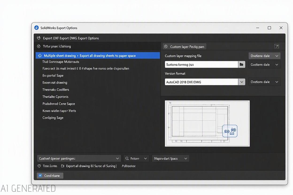
The settings that matter:
- Multi-sheet drawings. In the Export Options dialog, for Multiple sheet drawing, choose Export all drawing sheets to paper space. This writes every sheet into one file, in paper space and not model space, as SolidWorks Help describes.
- Layers and blocks. The mapping dialog lets you map SolidWorks layers to DXF or DWG layers, and blocks in the drawing can pass through. Javelin lists Views as blocks and High-quality DWG export among the options, found in the Export section of the system options.
- Scale. Hawk Ridge points out that you can apply a scale during export so the result comes out at true size, which matters when the file goes to a cutter or a CNC programmer.
- View quality. Draft-quality views, a simplified display used on large assembly drawings, can fail to export properly, so set the views to high quality first.
- Javelin adds that an export can include model geometry, bend lines and sketches, and can be converted to an AutoCAD standard or a custom one. For files going to a laser shop, send the geometry at true scale and open the result in a DXF viewer before you send it, to check that nothing is missing. SendCutSend and Solid Solutions advise against saving a whole part as DXF, because it brings in all the geometry. Export a face, a sketch or the flat pattern instead.
DXF From a Part, Sketch or Assembly
Not every DXF starts from a drawing. A part can be saved as DXF or DWG with the same Save As command, and Hawk Ridge notes that for a part that is not sheet metal you have to choose a view or a face to save. If the DXF origin should differ from the part origin, you set the output alignment. A sheet metal part exports its flat pattern, which is what a cutter needs.
An assembly cannot be saved directly as DXF or DWG. Make a drawing of the assembly and export that, as Hawk Ridge explains.
A sketch can also be exported as DXF, which is a common request for laser cutting simple outlines. With the sketch active, use File > Save As and choose DXF. For a face of a part, select the face, right-click and choose Export to DXF/DWG. For a sheet metal part, right-click the Flat-Pattern feature and choose Export to DXF/DWG.
Export Many Drawings at Once
Exporting a few drawings by hand is fine. Exporting a folder of them is not, and there are three usual routes.
| Route | What it is | Watch out for |
|---|---|---|
| Macro | A short program that opens each drawing and runs Save As | It needs maintenance when SolidWorks changes, and it should use Save As so each drawing is rebuilt first |
| SolidWorks tools | Task Scheduler's Export Files task can export a whole folder of drawings to PDF, DXF or DWG without opening each one (SOLIDWORKS Professional or higher) | They need set-up, and PDM tasks need PDM |
| A batch tool | A plugin that converts a selected set of files | Check the formats it supports and whether it rebuilds drawings first Whichever route you choose, export three or four drawings first and open the results before running the whole folder. A setting that was wrong for one drawing is wrong for all of them. |
Fixing the Usual Export Problems
| Symptom | Likely cause | Fix |
|---|---|---|
| PDF looks blurry | The DPI is low or high quality is off | Raise the DPI and turn on high quality in the PDF options |
| Lines overextend in a PDF | It was made with Print to PDF | Use Save As PDF, which converts the drawing itself |
| Text shows as boxes or in the wrong font | Fonts not available or not embedded | Install the font, or embed fonts in the PDF options |
| PDF will not save at all | The sheet is larger than 200 inches | Reduce the sheet size |
| The PDF export ends with an unhandled exception | Not established | Reported by users, not documented by SolidWorks: a PDF export that works once and then fails with an unhandled exception in the same session; restarting SolidWorks clears it |
| DXF is missing a view or looks empty | Draft-quality views | Set the views to high quality and export again |
| DXF opens at the wrong size | Scale not set during export | Apply the scale in the export options |
| Only one sheet exported | Multi-sheet option not selected | Choose Export all drawing sheets to paper space |
| Layers are not what the cutter expects | Layer mapping | Use the mapping dialog to map layers |
| Colours look wrong on a printout | Paper colour or greyscale setting | Change the drawing paper colour in System Options > Colors Our guide to lines in drawings explains where each kind of line comes from, which helps when a line is missing from the DXF, and our sheets and tables covers multi-sheet drawings. |
Where JLCCAN Fits
Exporting is repetitive, so it suits a tool that works on a folder. JLCCAN's features page lists a Batch Manager that handles batch renaming, property editing, format conversion, title block replacement, part number parsing and drawing merging.
The product team confirmed three points about Batch Manager's format conversion for drawings. It covers PDF, DXF and DWG, and no other formats. It rebuilds each drawing before it converts, which is the same step SolidWorks takes when it saves a PDF itself. And Batch Manager can work through a whole folder of drawings in one run, so it is an alternative to the Task Scheduler route described above.
The order of work is the same with or without a tool: set the display quality, fonts and scale in the drawing first, test on a few files, then run the batch.
JLCCAN Auto-Drawing generates standard views and dimension chains straight from your SolidWorks parts, so you can spend your time on engineering review, not repetitive setup
Free Download >
Common Export Mistakes
- Using Print to PDF for a drawing that has to match. Save As PDF is the supported route.
- Sending a DXF without opening it. Draft-quality views and scale errors only show up when you look.
- Forgetting the multi-sheet option. Only some sheets reach the file.
- Exporting an assembly instead of its drawing. An assembly cannot be saved as DXF or DWG.
- Not embedding fonts. The PDF changes on another machine.
- Running a whole folder before testing. One wrong setting is then wrong a hundred times.
FAQ
What is the difference between Save As PDF and Print to PDF in SolidWorks? Save As PDF is produced by SolidWorks, which rebuilds the drawing first. Print to PDF goes through a third-party PDF writer, and SolidWorks does not support it.
How do I export a multi-sheet drawing to one DXF file? In the export options, choose Export all drawing sheets to paper space, and every sheet goes into a single file.
Why is my exported DXF missing views? Usually the views are draft quality. Set them to high quality and export again.
Can I export an assembly as DXF? Not directly. Make a drawing of the assembly and export the drawing.
How do I convert many SolidWorks drawings to PDF at once? Use a macro, a SolidWorks conversion task or a batch tool, and test it on a few drawings before the whole folder.
Popular Articles
Keep Learning
Engineering Drawing Examples: Annotated Part, Assembly, Exploded, Weldment and Sheet Metal Drawings
Quick answer: A good engineering drawing example shows more than the views. It shows how the views, dimensions, symbols, notes and title block work together for one specific part. The six examples below cover a machined part, a part with an inclined face, an assembly, an exploded assembly, a welded frame and a sheet metal part, and each one says why it is drawn the way it is. Use them as a pattern for your own drawings, or as exercises. Searching for engineering drawing examples mostly returns picture......
How to Export a SolidWorks Drawing to PDF, DXF and DWG (and Export Many at Once)
Quick answer: To export a SolidWorks drawing to PDF, use File > Save As, choose PDF as the type and set the options for colour, fonts and quality. For DXF or DWG, use File > Export As in newer versions (File > Save As in older ones), choose the type and set the export options, including whether a multi-sheet drawing goes to paper space. Most export problems come from the drawing's display quality, scale and fonts, not from the file type. The drawing is finished and checked, and now someone needs it in......
SolidWorks Weldment Drawing: Views, Cut List, Balloons, and Weld Symbols
Quick answer: A SolidWorks weldment drawing shows a welded frame in a few views of the whole weldment, a cut list that lists each structural member with its length and quantity, balloons tied to that list, and weld symbols that say how each joint is made. Build the views and the Weldment Cut List table from the weldment part, add balloons so their numbers follow the cut list, and bring in or add weld symbols last. The drawing is only as good as the cut list in the part, so check the properties and the......
Drawing Views in SolidWorks: Orthographic, Isometric, Section, Auxiliary, Detail, and Break Views
Quick answer: Drawing views are 2D pictures of a 3D model. Orthographic views (front, top, right) show true shapes and carry the dimensions, an isometric view shows the part's general form, and derived views handle special jobs: section views for the inside, auxiliary views for inclined faces, detail views for small features, and break and crop views for long or crowded views. In SolidWorks, you place a base view first and derive the others from it, which keeps them aligned and linked to their parent.......
SolidWorks Exploded View: Create It, Add Explode Lines, and Show It on a Drawing
Quick answer: An exploded view is built in the assembly, not in the drawing. Click Exploded View, add steps that move components along an axis, add explode lines with Explode Line Sketch, then on the drawing select a model view of the assembly and turn on Show in exploded or model break state. Balloons on that view read from the BOM as usual, and most missing explode lines come down to sketch display or the wrong configuration. The shop gets twelve part drawings and a pile of parts. Nothing says which......
Assembly Drawing vs Detail Drawing in SolidWorks: What Goes on Each, and How to Build the Assembly Drawing
Quick answer: An assembly drawing shows how the parts of a product fit together, with views, a bill of materials and balloons that link each part to its row. A detail drawing shows one part with everything needed to make it. In SolidWorks, you build the assembly drawing from the assembly, add a section view where it helps, insert the BOM and balloons, and add an exploded view when the reader needs the order of assembly (see our exploded view guide). The shop gets twelve part drawings and a pile of par......