Engineering Drawing Examples: Annotated Part, Assembly, Exploded, Weldment and Sheet Metal Drawings
14 min
- What Makes a Good Engineering Drawing
- Example 1: A Machined Part Drawing
- Example 2: A Part With an Inclined Face
- Example 3: An Assembly Drawing
- Example 4: An Exploded Assembly Drawing
- Example 5: A Welded Frame
- Example 6: A Sheet Metal Part
- How to Read an Engineering Drawing Example
- Practice Drawings
- Common Mistakes in Drawings
- Where JLCCAN Fits
- FAQ
Quick answer: A good engineering drawing example shows more than the views. It shows how the views, dimensions, symbols, notes and title block work together for one specific part. The six examples below cover a machined part, a part with an inclined face, an assembly, an exploded assembly, a welded frame and a sheet metal part, and each one says why it is drawn the way it is. Use them as a pattern for your own drawings, or as exercises.
Searching for engineering drawing examples mostly returns pictures with no explanation, so it is hard to tell what makes one drawing good and another confusing. A drawing is good when a person who has never seen the part can make it, inspect it or assemble it without asking a question. The examples here are chosen to show that for six different kinds of drawing.
Each example comes with a short note on what to look at, and a link to the guide that explains the technique in full. All the parts are small and invented, which keeps the drawings readable.
Key Takeaways
- A drawing example is most useful when it explains why the views, dimensions and notes were chosen and not only what they look like.
- The six examples are a machined plate, a part with an inclined face, an assembly, an exploded assembly, a welded frame and a sheet metal part, each linked to the guide for its techniques.
- A bend note on a sheet metal flat pattern shows direction (UP or DOWN), angle and radius, and the exact wording is whatever SolidWorks generates.
- Auto-Drawing results on plate-type and block-type parts vary by user and sometimes need manual adjustment, and weldments are not supported.
What Makes a Good Engineering Drawing
Before the examples, here is the checklist they are measured against. It is the same for every type of drawing, and only the weight of each item changes.
| Item | What it should do |
|---|---|
| Views | Show every feature with the fewest views, and no view that repeats another |
| Dimensions | Define the part completely, once, from the datums the part actually uses |
| Tolerances and notes | Say how precise the part must be, and anything the drawing cannot show |
| Symbols | Use the standard's symbols for holes, finish, welds and datums, not look-alikes |
| Title block | Identify the drawing, its owner and its revision |
| BOM and balloons | On assemblies, tie every part in the views to its row in the list Our SolidWorks dimensioning covers the dimension rules in full, and our guide to drawing symbols and standards covers the symbols. |
Example 1: A Machined Part Drawing
The first example is the simplest and the most common: one machined part on one sheet. It is a 120 × 80 × 10 mm steel base plate with four clearance holes, two tapped holes and a small edge break. The numbers are invented.
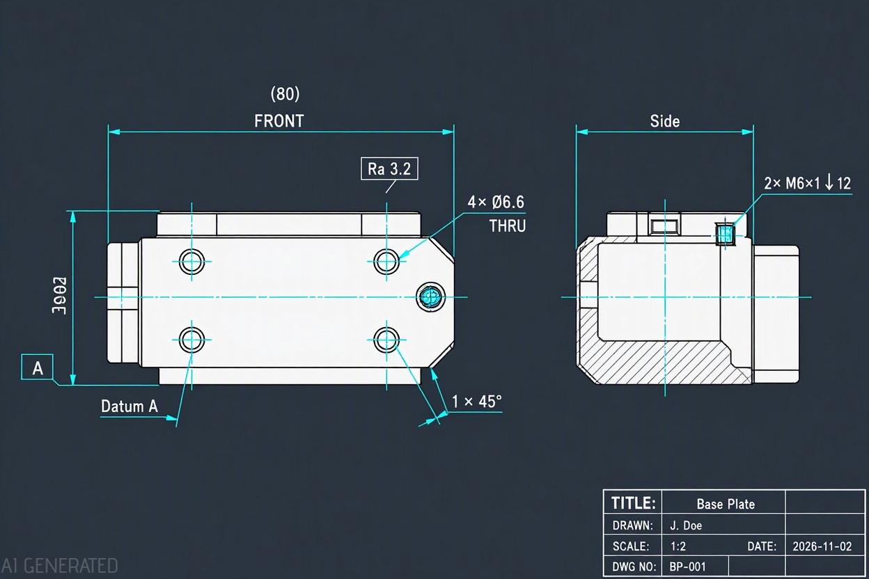
The drawing has a front view and a side view, and nothing more, because the plate has no feature that needs a third. The four clearance holes are one callout, 4× Ø6.6 THRU, and the two tapped holes are another, 2× M6×1 ↓ 12. The edge break is a single chamfer callout, 1 × 45°. Hole positions are measured from the left and bottom edges, because those are the faces the plate locates on, and the left edge is marked as datum A. One reference dimension, (80), sits between two of the holes as a check.
| What to notice | Why |
|---|---|
| Two views only | Every feature is visible, so a third view would repeat them |
| Holes called out once as a group | Repeating the diameter on each hole would give two numbers to maintain |
| Dimensions from the left and bottom edges | These are the datums the part locates on, not the sketch origin |
| Datum A marked on the left edge | A reader knows where the measurements start |
| (80) in parentheses | Information only, for checking after a revision |
| Surface finish symbol with Ra 3.2 | The machined face has a stated roughness limit The techniques behind it are in our Hole Wizard guide for the hole callouts, our chamfer dimension guide for the edge break, and our reference dimension guide for the parenthesised number. |
Example 2: A Part With an Inclined Face
The second example adds the views that a flat plate does not need. It is a bracket with a mounting face inclined at 30°, carrying a 40 × 10 mm slot and a Ø6.6 hole, plus a bored hole and a small corner round. The numbers are invented.
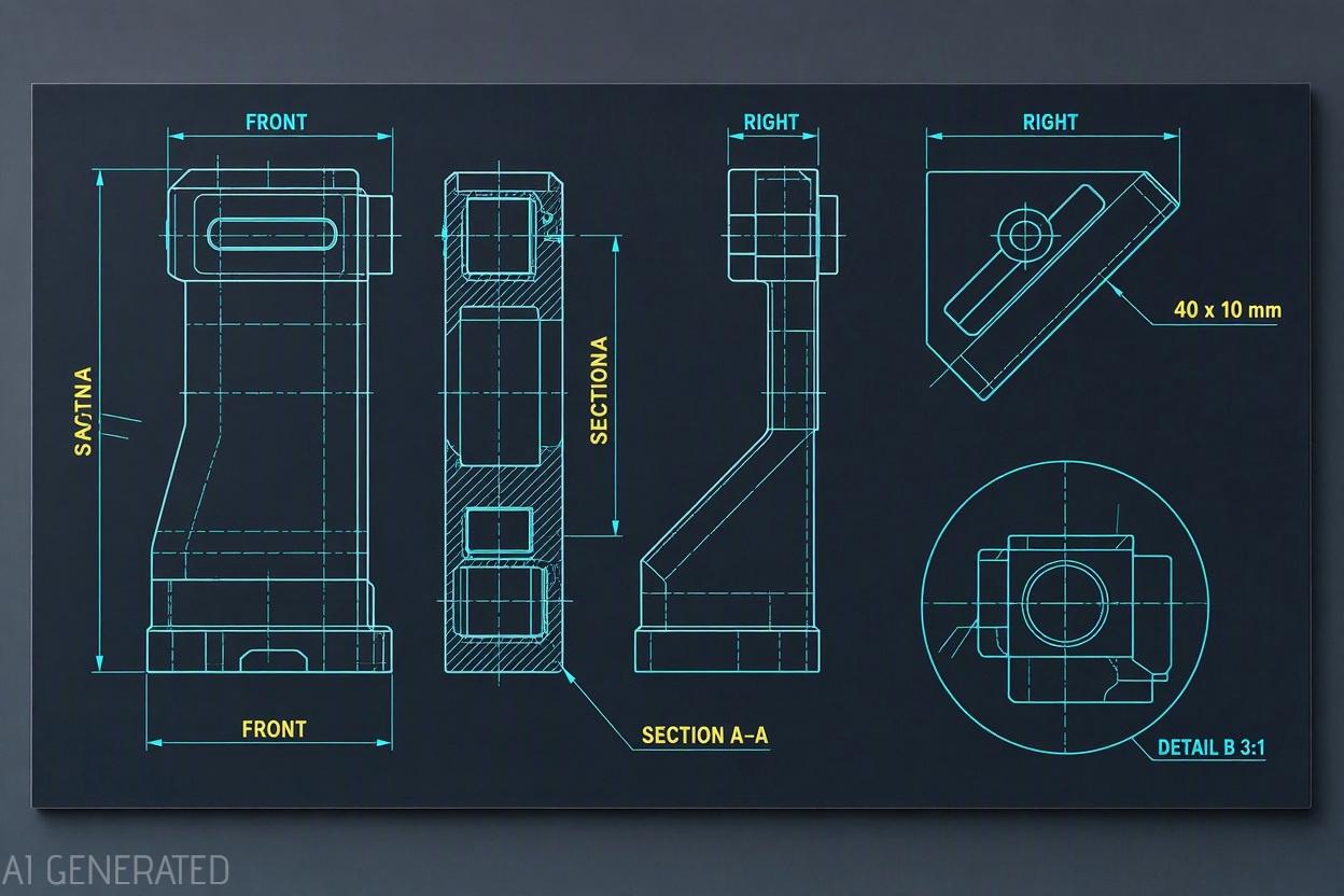
In the front view the slot would measure only about 34.6 mm and the hole would look like an ellipse, so the drawing adds a partial auxiliary view that shows the inclined face in true shape. A section through the bore shows the wall thickness and a thread that cannot be seen from outside, and a detail view at 3:1 shows the corner round, which is too small to read at the sheet scale. Each view answers a question the others cannot.
| View | What it shows | Why it is there |
|---|---|---|
| Front | The main profile and the inclined edge | Parent for the auxiliary view |
| Right | The height and the angle of the inclined face | Dimensions the 30° |
| Auxiliary, partial | The inclined face in true shape | Slot length and hole position can be dimensioned true |
| Section A–A through the bore | Wall thickness and the internal thread | Hidden lines would be too many to read |
| Detail B at 3:1 | The corner round | Too small at the sheet scale Our auxiliary view guide explains when an auxiliary view is worth adding and how to crop it to the face, and our drawing views guide covers the other view types. |
Example 3: An Assembly Drawing
An assembly drawing answers a different question from a part drawing. It does not say how each part is made. It says how the parts fit together and what to order. The example is a small mounting assembly: a base plate, a bracket, a clamp sub-assembly (a clamp arm and two M5 screws), four M6 screws with washers, and two dowel pins. The numbers are invented.
Sheet 1 carries the front, top and right views, one section through the dowel pins and the overall and mounting dimensions. The screws and pins are drawn whole in the section, because fasteners are not cut by convention. A bill of materials sits above the title block, and each part in the views has a balloon with its item number. Part dimensions are left to the detail drawings.
| Item | Part number | Description | Material | Qty |
|---|---|---|---|---|
| 1 | MB-1001 | Base plate | Steel S355 | 1 |
| 2 | MB-1002 | Bracket | Aluminium 6061 | 1 |
| 3 | MB-2000 | Clamp subassembly | n/a | 1 |
| 4 | ISO 4762 M6×16 | Socket head cap screw | Steel 8.8 | 4 |
| 5 | ISO 7089 M6 | Washer | Steel | 4 |
| 6 | ISO 2338 6×20 | Dowel pin | Steel | 2 What to notice is how little dimensioning there is. Only the overall size and the interface dimensions appear, and the BOM does the work of identifying parts. Our assembly drawing guide explains what goes on an assembly drawing and what stays on the detail drawings, and our BOM guide shows the three BOM types. |
Example 4: An Exploded Assembly Drawing
The fourth example shows the same mounting assembly with its parts pulled apart. An exploded view answers the question an assembly drawing leaves open: in what order do the parts go together. It is usually a separate sheet, an isometric view of the exploded assembly with balloons and a Parts only BOM, so every loose part has a number.
| Explode step | Components | Why this order |
|---|---|---|
| 1 | Four M6 screws | They go in last, so they come out first |
| 2 | Four M6 washers | They sit under the screw heads |
| 3 | Bracket | It sits on the plate and dowel pins |
| 4 | Two dowel pins | They locate the bracket |
| 5 | Clamp sub-assembly | It attaches to the bracket's side Dashed explode lines run from each screw through its washer to the hole, from each dowel pin to its hole and from the clamp to its seat. Without them the reader cannot tell which hole a screw belongs to. Our exploded view guide covers how the view is built and why explode lines sometimes go missing. |
Example 5: A Welded Frame
A welded frame is drawn differently again, because it is one part made of several pieces. The example is a small equipment stand made of 40 × 40 × 3 mm square tube, 600 mm long and 400 mm wide overall: four legs, two long rails, two short rails, four corner gussets and four foot caps. The numbers are invented.
Sheet 1 shows the whole frame in a few views, with a cut list in place of a BOM. The cut list gives each member once, with its profile, length and quantity, and balloons tie the members in the views to its rows. A second sheet shows one leg and one rail square-on, with cuts and holes, and weld symbols state the size and type of each joint.
| Item | Description | Profile | Length (mm) | Qty |
|---|---|---|---|---|
| 1 | Leg | Square tube 40 × 40 × 3 | 500 | 4 |
| 2 | Long rail | Square tube 40 × 40 × 3 | 520 | 2 |
| 3 | Short rail | Square tube 40 × 40 × 3 | 320 | 2 |
| 4 | Corner gusset | Plate 3 mm | n/a | 4 |
| 5 | Foot cap | Plate 3 mm | n/a | 4 The rails are 520 and 320 mm because they fit between the legs. Our weldment drawing guide covers the cut list, the balloons and how to read and add weld symbols. |
Example 6: A Sheet Metal Part
The last example is a sheet metal bracket: a 2 mm steel L-shaped part with one 90° bend and two mounting holes. The numbers are invented. A sheet metal drawing usually carries two views of the same part, the formed part and its flat pattern, because the shop cuts it flat and bends it afterwards.
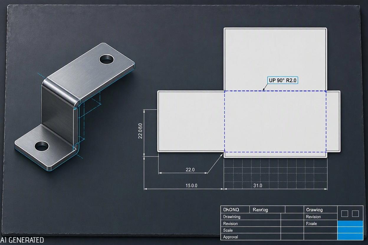
The flat pattern view shows the part laid out with bend lines and a bend note that gives the direction, angle and radius. The thickness, material and finish go in the title block or a note, since they apply to the whole part. Hole positions are dimensioned on the flat pattern from the datum edge, because that is how the blank is cut.
| What to notice | Why |
|---|---|
| A formed view and a flat pattern view | Bending and cutting are different operations |
| Bend lines and bend notes on the flat pattern | They tell the shop where, which way and how far to bend |
| Thickness and material stated once | They apply to every feature |
| Holes dimensioned on the flat pattern | The blank is cut before it is bent If the bend lines do not show on a flat pattern, the cause is almost always a display setting rather than the model, and our [lines guide, LINK: add when published] sorts out where each kind of line comes from. |
How to Read an Engineering Drawing Example
The same reading order works on every example above, and on any real drawing.
- Start with the title block. It says what the part is, who owns it and which revision you hold.
- Find the views. Work out which direction each one looks from, and check the projection symbol so you know whether first or third angle applies.
- Read the dimensions. Look for the datums first, then the sizes and locations measured from them.
- Check the symbols and notes. Holes, finish, welds, datums and general notes say what the views cannot.
- For an assembly, read the list and the balloons. They say what each part is and how many are needed.
- Our title block guide describes the fields in step 1.
Practice Drawings
The examples work as exercises if you rebuild them yourself. Each exercise below matches one of the examples, and the aim of each is the technique, not the exact numbers.
- Plate. Model the base plate, make the drawing, and choose the datums before placing any dimension.
- Bracket. Add the inclined face and make a partial auxiliary view, then dimension the slot in that view.
- Assembly. Build the mounting assembly, insert a BOM and balloons, and use Section Scope so the fasteners are not cut.
- Exploded view. Add an exploded view with explode lines and show it on a second sheet.
- Welded frame. Model the frame as a weldment and produce its cut list and balloons.
- Check each exercise against the example: could someone who has never seen the part make it from your drawing alone?
Common Mistakes in Drawings
- Showing every view whether it is needed or not. Each view should answer a question.
- Dimensioning from the edge that was easiest to sketch from. Use the datums the part locates on.
- Repeating a dimension. Give each feature one number, in the view where it appears true.
- Using symbols from a chart for the wrong discipline. Mechanical drawings use mechanical symbols.
- Leaving the title block half empty. Revision and owner are the fields people miss.
- Typing values that exist in the model. They go stale at the next revision.
- Copying a drawing from the web. Its standard, units and projection may not match yours.
Where JLCCAN Fits
JLCCAN's Auto-Drawing generates a drawing from a 3D model. According to its features page it detects the main view, scales the views to the sheet, and applies dimensions, dimension chains, hole tables and surface finish annotations to parts in batch. It suits plate-type and block-type parts best, and the JLCCAN help-centre FAQ says the same: automatic dimensioning currently works best on the plate-type and block-type parts common in non-standard automation equipment. For assemblies it generates the standard three views only, with no automatic dimensioning or annotation, so the assembly, exploded and weldment examples above still need manual work.
According to JLCCAN's product team, how much Auto-Drawing produces depends on the part and on your own standards, and you adjust by hand whatever does not suit you. For these two examples that means the views are the standard views and an isometric. It does not add section, detail or auxiliary views on parts, so the bracket's auxiliary view is made by hand, and its annotations follow the GB standard.
JLCCAN Auto-Drawing generates standard views and dimension chains straight from your SolidWorks parts, so you can spend your time on engineering review, not repetitive setup
Free Download >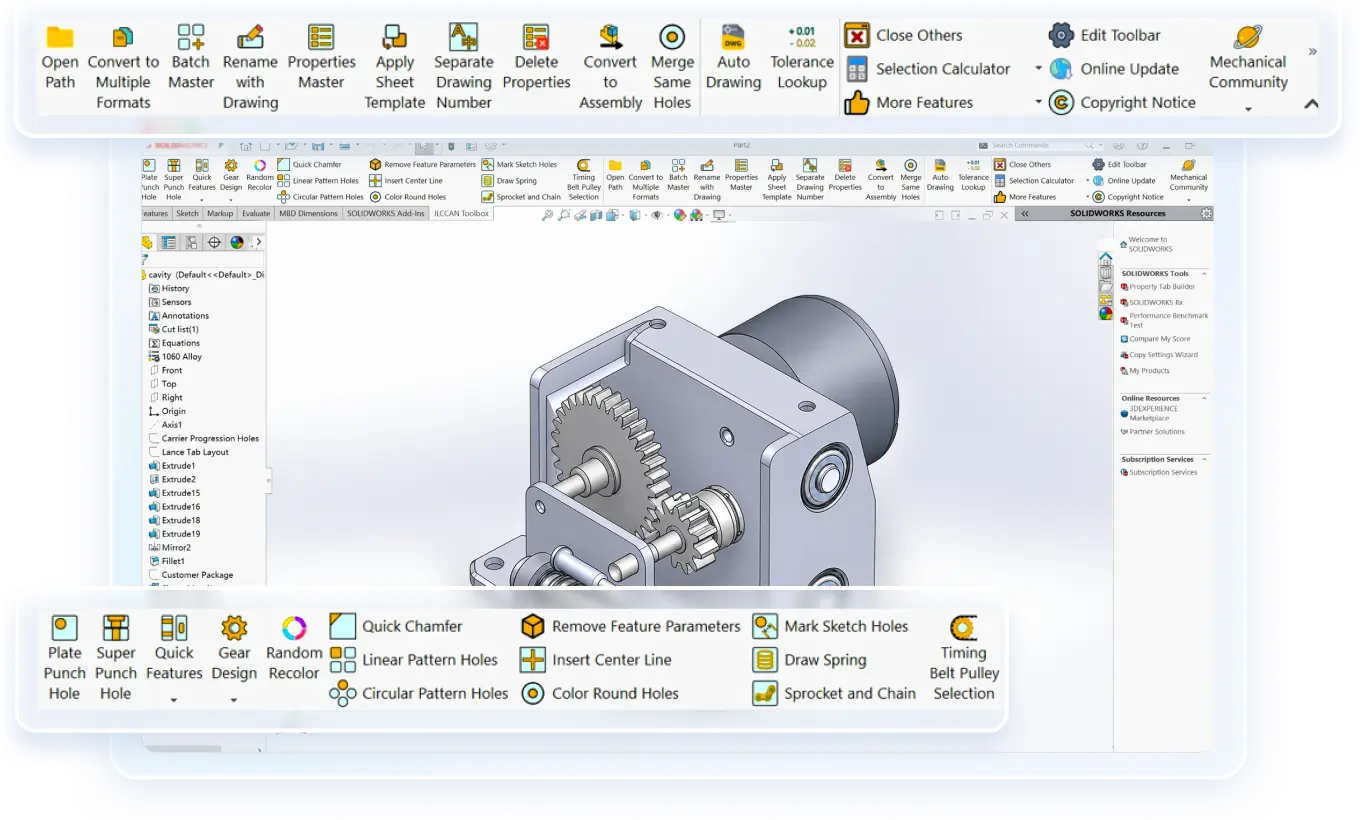
FAQ
What should an engineering drawing include? The views needed to show every feature, complete dimensions and tolerances, the symbols and notes for holes, finish and welds, a title block with the owner and revision, and, for assemblies, a bill of materials and balloons.
How many views does a mechanical drawing need? As few as remove ambiguity, usually two or three orthographic views and sometimes an isometric. Add a section, detail or auxiliary view only when it shows something the others cannot.
What is the difference between a part drawing and an assembly drawing? A part drawing describes one part in full so it can be made and inspected. An assembly drawing shows how several parts fit together. See our assembly drawing guide.
What is an exploded drawing used for? It shows the order in which the parts of an assembly go together, with lines to the positions they come from, so an assembler or service technician can follow it.
Can I use these drawings as templates? They are patterns for how to lay a drawing out, not files to download. Build the same layouts from your own models, and set the standard and title block in your drawing template.
Popular Articles
Keep Learning
Engineering Drawing Examples: Annotated Part, Assembly, Exploded, Weldment and Sheet Metal Drawings
Quick answer: A good engineering drawing example shows more than the views. It shows how the views, dimensions, symbols, notes and title block work together for one specific part. The six examples below cover a machined part, a part with an inclined face, an assembly, an exploded assembly, a welded frame and a sheet metal part, and each one says why it is drawn the way it is. Use them as a pattern for your own drawings, or as exercises. Searching for engineering drawing examples mostly returns picture......
How to Export a SolidWorks Drawing to PDF, DXF and DWG (and Export Many at Once)
Quick answer: To export a SolidWorks drawing to PDF, use File > Save As, choose PDF as the type and set the options for colour, fonts and quality. For DXF or DWG, use File > Export As in newer versions (File > Save As in older ones), choose the type and set the export options, including whether a multi-sheet drawing goes to paper space. Most export problems come from the drawing's display quality, scale and fonts, not from the file type. The drawing is finished and checked, and now someone needs it in......
SolidWorks Weldment Drawing: Views, Cut List, Balloons, and Weld Symbols
Quick answer: A SolidWorks weldment drawing shows a welded frame in a few views of the whole weldment, a cut list that lists each structural member with its length and quantity, balloons tied to that list, and weld symbols that say how each joint is made. Build the views and the Weldment Cut List table from the weldment part, add balloons so their numbers follow the cut list, and bring in or add weld symbols last. The drawing is only as good as the cut list in the part, so check the properties and the......
Drawing Views in SolidWorks: Orthographic, Isometric, Section, Auxiliary, Detail, and Break Views
Quick answer: Drawing views are 2D pictures of a 3D model. Orthographic views (front, top, right) show true shapes and carry the dimensions, an isometric view shows the part's general form, and derived views handle special jobs: section views for the inside, auxiliary views for inclined faces, detail views for small features, and break and crop views for long or crowded views. In SolidWorks, you place a base view first and derive the others from it, which keeps them aligned and linked to their parent.......
SolidWorks Exploded View: Create It, Add Explode Lines, and Show It on a Drawing
Quick answer: An exploded view is built in the assembly, not in the drawing. Click Exploded View, add steps that move components along an axis, add explode lines with Explode Line Sketch, then on the drawing select a model view of the assembly and turn on Show in exploded or model break state. Balloons on that view read from the BOM as usual, and most missing explode lines come down to sketch display or the wrong configuration. The shop gets twelve part drawings and a pile of parts. Nothing says which......
Assembly Drawing vs Detail Drawing in SolidWorks: What Goes on Each, and How to Build the Assembly Drawing
Quick answer: An assembly drawing shows how the parts of a product fit together, with views, a bill of materials and balloons that link each part to its row. A detail drawing shows one part with everything needed to make it. In SolidWorks, you build the assembly drawing from the assembly, add a section view where it helps, insert the BOM and balloons, and add an exploded view when the reader needs the order of assembly (see our exploded view guide). The shop gets twelve part drawings and a pile of par......