Title Block in Engineering Drawings: What It Contains, Standards, and Examples
10 min
- What Is a Title Block
- What Goes in a Title Block
- Title Block Standards: ISO 7200 and ASME
- Title Block Size and Position by Sheet Size
- Title Block Examples
- Common Title Block Mistakes
- Where SolidWorks Fits
- FAQ
Quick answer: A title block is the boxed area, usually in the bottom right corner of a drawing sheet, that identifies the drawing and says who owns it, who approved it and what revision it is. ISO 7200 sets the data fields (an identification number, a title and the legal owner are the basics) and ASME Y14.1 and Y14.100 cover the same ground for U.S. drawings. Mechanical drawings usually add revision, scale, sheet number, material, general tolerances and the projection symbol.
Someone opens a drawing from the archive, and the part looks right. Nothing on the sheet says which revision it is, who approved it or which company owns it, so nobody can tell whether it is the one that was released. The geometry was fine. The title block was empty.
This guide explains what a title block is, which fields it carries, what ISO 7200 and the ASME standards ask for, how big it is and where it goes, and what a finished block looks like on a part drawing and on an assembly drawing. For setting one up in SolidWorks, see our drawing template guide.
Key Takeaways
- A title block identifies the drawing, and its basic fields are an identification number, a title and the legal owner, usually placed in the lower right corner.
- Its content and layout come from the drafting standard, ISO 7200 and ISO 5457 or the ASME Y14 series, so the edition your customer specifies is the one to follow.
- A part drawing and an assembly drawing fill the same fields with different values, which the two examples in the guide show side by side.
- In SolidWorks the fields can be linked to custom properties so they fill from the model, which the template guide covers.
What Is a Title Block
A title block is the part of a drawing sheet that holds the administrative information about the drawing. It sits inside the border, normally at the bottom right, and it carries what a reader needs to interpret, identify and file the drawing. Roy Mech's notes on ISO 7200 put it as the information that enables the drawing to be interpreted, identified and archived, which is why a drawing without one is only a picture.
Two neighbouring blocks are easy to mix up with it. The revision block is a separate table that records each change to the drawing, and it sits at the top right of the sheet in ASME practice or beside the title block. On assembly drawings a parts list or bill of materials is attached above the title block. They share the sheet and often share fields, but each has its own job.
What Goes in a Title Block
Which fields a title block carries depends on your standard and your company, and a mechanical part drawing usually has the ones below. The last column says how the value is normally produced, which decides how much typing you do.
| Field | Typical content | Where the value should come from |
|---|---|---|
| Title / description | Part name | The model's description |
| Drawing or part number | Unique ID | The model or the file name |
| Material | Steel, aluminium grade | The model, so the BOM and the drawing agree |
| Finish / treatment | Anodize, zinc plating | The model |
| Revision | Current revision letter | The drawing's own record |
| Scale | 1:2, 1:1 | The sheet or view |
| Sheet | 1 of 3 | The drawing |
| Drawn by / checked by / approved by, dates | Names and dates | The drawing record, or typed |
| General tolerances | ±0.1 mm up to 30 mm | Written once in the standard block |
| Projection symbol | First angle or third angle | The sheet setup |
| Company name, logo, owner | Fixed text and image | The sheet format Typing the same part number into the model, the drawing and the BOM invites mismatches, so any value that already exists in the model should be read from it instead of retyped. Roy Mech's notes add that mechanical drawings should say which standards they follow for surface texture, welds, general tolerances and geometric tolerances, either in the block or in a note beside it. |
Title Block Standards: ISO 7200 and ASME
Two families of standards cover title blocks, and they overlap more than they differ.
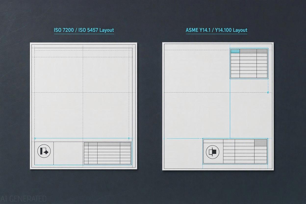
ISO 7200 defines the data fields used in title blocks and document headers. The basic fields are an identification (registration) number, the title and the legal owner, and the standard also covers dates, the people responsible and revision information. It does not by itself fix where the block sits. ISO 5457 covers the sizes and layout of drawing sheets, and it places the title block at the bottom right. Roy Mech notes that the basic fields should sit in a rectangle at most 170 mm wide.
ASME spreads the same ground over three standards. ASME Y14.1 (decimal inch) and Y14.1M (metric) cover sheet sizes and the layout of the title block, with separate layouts for the size groups and a shorter continuation-sheet block for later sheets. ASME Y14.100 covers engineering drawing practices, including what the markings and identification mean, and ASME Y14.35 covers revisions. Y14.1 introduced a design activity identification field in place of the CAGE code in its 2012 edition.
| Topic | ISO | ASME |
|---|---|---|
| Title block data fields | ISO 7200 | Y14.100 (content), Y14.1 / Y14.1M (layout) |
| Sheet sizes and layout | ISO 5457 | Y14.1 / Y14.1M |
| Position | Bottom right (ISO 5457) | Bottom right, with the revision block at the top right |
| Revision handling | Revision field in ISO 7200 | Y14.35 and the revision history block |
| Continuation sheets | Shorter block on later sheets is common practice | Defined as a continuation-sheet block in Y14.1 A drawing should follow one family throughout, with the block, the projection symbol and the notation consistent with it. Our guide to drawing symbols and standards explains how to choose. |
Title Block Size and Position by Sheet Size
The sheet size decides the room available for the block, and the standards define the common sizes. These are the ones you will meet.
| ISO series | Size (mm) | ANSI series | Size (in) |
|---|---|---|---|
| A4 | 210 × 297 | A | 8.5 × 11 |
| A3 | 297 × 420 | B | 11 × 17 |
| A2 | 420 × 594 | C | 17 × 22 |
| A1 | 594 × 841 | D | 22 × 34 |
| A0 | 841 × 1189 | E | 34 × 44 On ISO sheets the basic fields sit in a rectangle of up to 170 mm wide at the bottom right, so the same width of block can be used from A4 to A0. ASME Y14.1 gives title block layouts for groups of sizes instead of one fixed width, and the exact dimensions are in the standard, which this guide does not reproduce. If you need to build a block to the dimensions, take them from your copy of the standard or your customer's template. Position matters less than it looks, and the reason is practical. A drawing that is folded for filing ends up with the bottom right corner showing, so the block is what you can read without unfolding the sheet. |
Title Block Examples
The two examples below use the plate and the mounting assembly from our other guides. The values are invented.
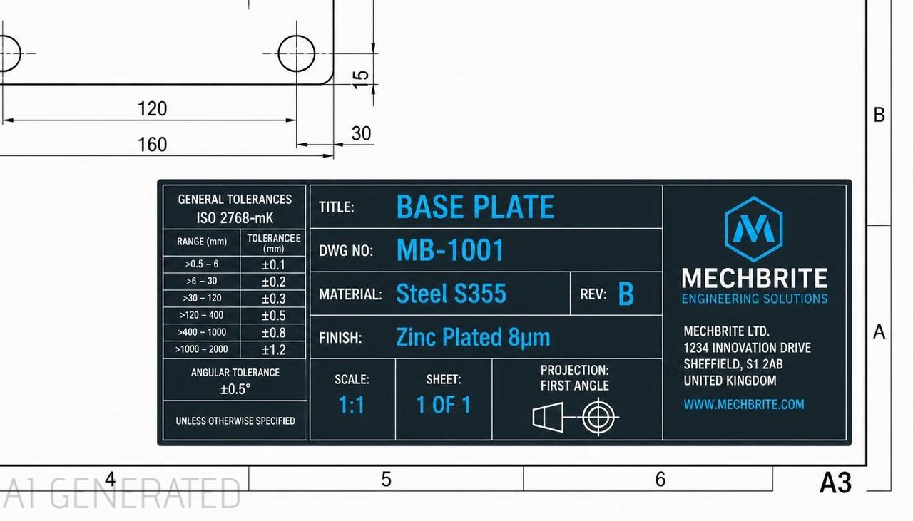
A part drawing
| Field | Value |
|---|---|
| Title | BASE PLATE |
| Drawing number | MB-1001 |
| Material | Steel S355 |
| Finish | Zinc plated, 8 µm |
| Revision | B |
| Scale | 1:1 |
| Sheet | 1 of 1 |
| Drawn / checked / approved | Initials and dates |
| General tolerances | ±0.1 mm up to 30 mm, ±0.2 mm above |
| Projection | First angle symbol |
| Owner | Company name and logo A part drawing has one material and one finish, so both go in the block. The reader can find everything needed to order the blank and the surface treatment without opening the model. |
An assembly drawing
| Field | Value |
|---|---|
| Title | MOUNTING ASSEMBLY |
| Drawing number | MB-0100 |
| Material | See BOM |
| Revision | A |
| Scale | 1:2 |
| Sheet | 1 of 3 |
| Drawn / checked / approved | Initials and dates |
| Projection | First angle symbol |
| Owner | Company name and logo An assembly has no single material, so the field points at the bill of materials, which sits above the block. Sheets 2 and 3 carry the continuation block, with the drawing number, sheet and revision only. Our assembly drawing guide shows how the sheets are planned. |
Common Title Block Mistakes
- Leaving the legal owner out. It is one of the basic fields, and without it the drawing has no stated owner.
- Typing values that exist in the model. Part numbers and materials typed by hand drift away from the model at the next revision.
- Forgetting the revision. A drawing that does not say which revision it is cannot be matched to a release.
- Using the wrong projection symbol. The symbol and the view layout must agree.
- Mixing conventions. An ISO sheet with ASME notation, or the reverse, leaves the reader guessing.
- Showing one scale on a sheet that has several. If views use different scales, the block should say so, and each view should carry its own label.
- Making the block too crowded. Fields that are not needed on every drawing belong in a note, so the block stays readable.
- Copying another company's block. The owner, logo and field set are specific to the organisation.
Where SolidWorks Fits
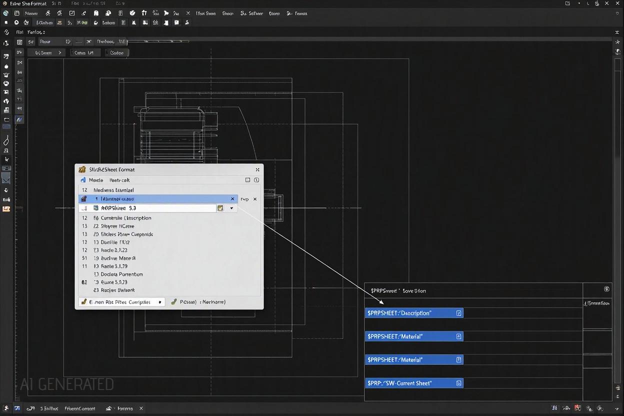
In SolidWorks the title block is part of the sheet format, and its fields can read the model's properties so the values are not typed. Our drawing template guide covers how the drawing template, sheet format and drawing relate, how to link fields with $PRPSHEET and $PRP, and how to change a block across many existing drawings.
JLCCAN Auto-Drawing generates standard views and dimension chains straight from your SolidWorks parts, so you can spend your time on engineering review, not repetitive setup
Free Download >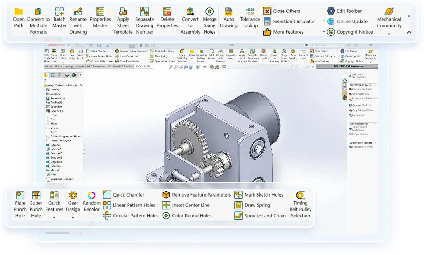
FAQ
What is a title block? The boxed area of a drawing sheet, usually at the bottom right, that identifies the drawing and shows the owner, the people who approved it and the revision.
What information must be in a title block? It depends on your standard or customer. ISO 7200 treats the identification number, the title and the legal owner as the basics, and mechanical drawings usually add revision, scale, sheet number, material, general tolerances and the projection symbol.
Where does the title block go on a drawing? At the bottom right of the sheet. ISO 5457 and the ASME formats both place it there.
What is the difference between a title block and a revision block? The title block identifies the drawing. The revision block records each change made to it, and in ASME practice it sits at the top right of the sheet or beside the title block.
How do I change a title block in SolidWorks? Edit the sheet format and update the fields, and for many drawings use a batch method. Our template guide has the steps.
Popular Articles
Keep Learning
Engineering Drawing Examples: Annotated Part, Assembly, Exploded, Weldment and Sheet Metal Drawings
Quick answer: A good engineering drawing example shows more than the views. It shows how the views, dimensions, symbols, notes and title block work together for one specific part. The six examples below cover a machined part, a part with an inclined face, an assembly, an exploded assembly, a welded frame and a sheet metal part, and each one says why it is drawn the way it is. Use them as a pattern for your own drawings, or as exercises. Searching for engineering drawing examples mostly returns picture......
How to Export a SolidWorks Drawing to PDF, DXF and DWG (and Export Many at Once)
Quick answer: To export a SolidWorks drawing to PDF, use File > Save As, choose PDF as the type and set the options for colour, fonts and quality. For DXF or DWG, use File > Export As in newer versions (File > Save As in older ones), choose the type and set the export options, including whether a multi-sheet drawing goes to paper space. Most export problems come from the drawing's display quality, scale and fonts, not from the file type. The drawing is finished and checked, and now someone needs it in......
SolidWorks Weldment Drawing: Views, Cut List, Balloons, and Weld Symbols
Quick answer: A SolidWorks weldment drawing shows a welded frame in a few views of the whole weldment, a cut list that lists each structural member with its length and quantity, balloons tied to that list, and weld symbols that say how each joint is made. Build the views and the Weldment Cut List table from the weldment part, add balloons so their numbers follow the cut list, and bring in or add weld symbols last. The drawing is only as good as the cut list in the part, so check the properties and the......
Drawing Views in SolidWorks: Orthographic, Isometric, Section, Auxiliary, Detail, and Break Views
Quick answer: Drawing views are 2D pictures of a 3D model. Orthographic views (front, top, right) show true shapes and carry the dimensions, an isometric view shows the part's general form, and derived views handle special jobs: section views for the inside, auxiliary views for inclined faces, detail views for small features, and break and crop views for long or crowded views. In SolidWorks, you place a base view first and derive the others from it, which keeps them aligned and linked to their parent.......
SolidWorks Exploded View: Create It, Add Explode Lines, and Show It on a Drawing
Quick answer: An exploded view is built in the assembly, not in the drawing. Click Exploded View, add steps that move components along an axis, add explode lines with Explode Line Sketch, then on the drawing select a model view of the assembly and turn on Show in exploded or model break state. Balloons on that view read from the BOM as usual, and most missing explode lines come down to sketch display or the wrong configuration. The shop gets twelve part drawings and a pile of parts. Nothing says which......
Assembly Drawing vs Detail Drawing in SolidWorks: What Goes on Each, and How to Build the Assembly Drawing
Quick answer: An assembly drawing shows how the parts of a product fit together, with views, a bill of materials and balloons that link each part to its row. A detail drawing shows one part with everything needed to make it. In SolidWorks, you build the assembly drawing from the assembly, add a section view where it helps, insert the BOM and balloons, and add an exploded view when the reader needs the order of assembly (see our exploded view guide). The shop gets twelve part drawings and a pile of par......