SolidWorks Drawing Template and Sheet Format: How to Set Up, Link Properties, and Update Old Drawings
12 min
- What the Title Block Needs From SolidWorks
- Template, Sheet Format, and Drawing: Three Layers
- How to Build a Template That Fills Itself In
- Link the Title Block to Custom Properties
- Edit a Title Block on an Existing Drawing
- Updating a Title Block Across Many Drawings
- Common Template and Title Block Mistakes
- FAQ
Quick answer: A SolidWorks drawing is built from three layers. The drawing template (.drwdot) starts a new drawing, the sheet format (.slddrt) holds the border and title block, and the drawing file (.slddrw) is the result. To set up a title block that fills itself in, put the border and fields in Edit Sheet Format, link each field to a custom property with $PRPSHEET or $PRP, save the sheet format, then save the template that points to it. Old drawings do not update on their own when you change the title block later, which is the part that costs the most time.
Someone changes the company logo or adds a "Material" field to the title block. A month later the new drawings look right, and several hundred old ones still carry the old block. Nothing in SolidWorks is broken. The template only applies to drawings created after the change.
This guide covers what the title block needs from SolidWorks, how SolidWorks splits template, sheet format and drawing, how to build a template that fills in its own fields, how to edit or swap a title block on an existing drawing, and what to do when a lot of drawings need the new one. For what a title block should contain in general, see our title block guide.
Key Takeaways
- A template, a sheet format and a drawing are three separate layers, and knowing which layer a setting belongs to explains most cases where a change does not carry over.
- Linking title block fields to custom properties lets the title block fill itself from the model instead of being typed, which removes a common source of stale values.
- A revision table cannot be saved in a sheet format and has to live in the template or the drawing, while custom properties do travel with the sheet format.
- Replacing the title block on many drawings is a batch job, and whether linked fields survive depends on how the template is set up, so test on one drawing first.
What the Title Block Needs From SolidWorks
The title block is the area, usually in the bottom right corner of the sheet, that identifies the drawing and shows who owns it, who approved it and what revision it is. Which fields it carries depends on your standard, and our title block guide, LINK: add when published] covers that, along with sheet sizes. What matters for setup is where each field gets its value, because that decides how much typing you do later.
| Field | Best source in SolidWorks |
|---|---|
| Title / description | Model custom property, linked with $PRPSHEET |
| Drawing or part number | Model property or file name (system property) |
| Material | Model property, so the BOM and the drawing agree |
| Finish / treatment | Model property |
| Revision | Drawing property, linked with $PRP |
| Scale | System property of the sheet |
| Sheet | System property of the sheet |
| Drawn by / checked by / approved by, dates | Drawing properties, or typed |
| General tolerances | Typed once in the template |
| Projection symbol | Sheet property, saved in the template |
| Company name, logo, owner | Typed or placed once in the sheet format Typing the same part number into the model, the drawing and the BOM invites mismatches. A title block that reads from the model's properties removes that class of error. Sheet size is a separate choice, made in the sheet properties, and the common ISO and ANSI sizes are listed in the title block guide. |
Template, Sheet Format, and Drawing: Three Layers
The confusion in SolidWorks comes from the naming. There are three files, and each one holds different things.
| Layer | Extension | What it holds | Created by |
|---|---|---|---|
| Drawing template | .drwdot | Sheet properties (projection type, scale), predefined views, extra sheets, and a link to a sheet format | File > Save As, type .drwdot |
| Sheet format | .slddrt | Page size and orientation, border, title block, standard text, logos | File > Save Sheet Format |
| Drawing | .slddrw | Your actual views and dimensions, started from the template | New drawing Three details from SolidWorks Help and reseller documentation matter in practice. |
- A drawing can use a different sheet format on each sheet. One drawing can hold an A3 sheet and an A4 sheet with different title blocks.
- Some settings live in the template, not the sheet format. The type of projection and other sheet properties are saved in the drawing or template, so a sheet format file on its own will not set first or third angle.
- A revision table cannot be saved in a sheet format. Put it in the template or the drawing.
- A template can be saved with a sheet format linked or without one. If it has none, SolidWorks asks you to pick a format each time you start a drawing. If the link points to a path that no longer exists, you get the error that the sheet format could not be located.
How to Build a Template That Fills Itself In
The order matters, because the template links to the sheet format file. Doing it in this order avoids the broken-link error.
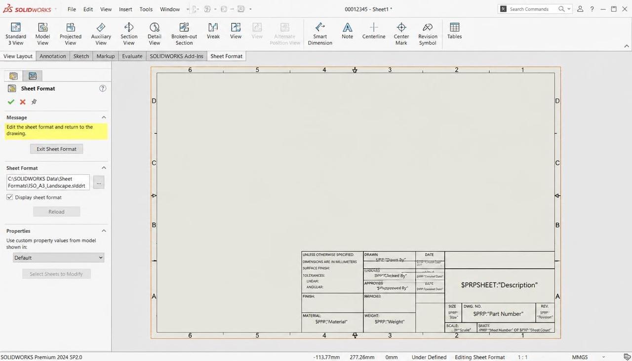
- Set the sheet properties. Right-click the drawing sheet and choose Properties. Pick the sheet size, scale and type of projection.
- Edit the sheet format. Right-click anywhere on the sheet and choose Edit Sheet Format. Draw the border, add the title block lines and place notes for each field. Anything you draw here is part of the sheet format, so keep the working views out of it.
- Link the fields to properties. See the next section. Do this while still in Edit Sheet Format.
- Save the sheet format. Choose File > Save Sheet Format and save the .slddrt in a shared folder that every user can reach. Do not rely on the default install folder, which can change between versions and machines.
- Link the template to that file. Go back to the sheet properties, browse to the .slddrt you just saved and apply it.
- Save the template. Choose File > Save As and set the type to Drawing Templates (.drwdot). Save it in a shared folder too.
- Point SolidWorks at the folders. In Tools > Options > System Options > File Locations, add your template folder under Document Templates and your sheet format folder under Sheet Formats, so they appear when users start a new drawing. Menu names can differ slightly between versions.
- Test it. Make a new drawing from a part that has its properties filled in, and check that every field shows a value.
- A practical point on step 4. The sheet format and the template are linked by path. If the template sits on a shared drive and the sheet format sits in someone's local folder, the template will work for that person and fail for everyone else. Keep both in the same shared location from the start.
Link the Title Block to Custom Properties
A typed title block works for one drawing. A linked one works for all of them. SolidWorks notes can pull a value from a custom property, and two link types cover almost every title block.
| Link | Reads from | Example | Use for |
|---|---|---|---|
| $PRPSHEET | The model shown in the view named in the sheet properties | $PRPSHEET:"Description" | Part name, number, material, finish |
| $PRP | The drawing file itself | $PRP:"Revision" | Revision, drawn by, approval dates To add one, enter Edit Sheet Format, create a note, and use Link to Property in the Note PropertyManager. You can also type the link text directly. If the property value changes in the model, the title block updates in the drawing. Three things commonly go wrong. |
- No view on the sheet yet. $PRPSHEET needs a model to read from. By default SolidWorks uses the model in the first view placed on the sheet. A template with no views will show blank fields until the first view is inserted, which is normal.
- The property does not exist on the model. The link is valid but the model has no property with that name, so the field stays empty. Add the same property names to your part and assembly templates, so every new model starts with them. SolidWorks also saves the document's custom properties with a sheet format and adds them to new documents that use it.
- Different models on one sheet. In a multi-sheet drawing with views of different models, the sheet properties decide which model each sheet reads from. If a title block shows the wrong part number, check which view the sheet is pointing to.
- If you cannot find an empty linked note on the sheet, choose View > Annotation Link Variables, which shows the link variable names so an empty linked note is easier to find.
Edit a Title Block on an Existing Drawing
To change the title block on one drawing, right-click the sheet and choose Edit Sheet Format, change the text or lines, then exit the mode. Two points come up often.
- The change stays in that drawing. The template and the saved .slddrt are untouched. If the change should apply to future drawings, save the sheet format again and re-save the template.
- You can only select the title block in edit mode. Outside Edit Sheet Format the border and title block are locked as background. Edit Sheet is the opposite mode and returns you to the views.
- To swap in a different sheet format on one drawing, open the sheet properties, browse to another .slddrt and apply it. This is also how you move a drawing from an A4 format to A3. Check the views afterwards, because the sheet size changes but the view placement does not.
Updating a Title Block Across Many Drawings
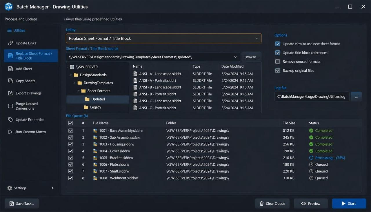
This is the part that takes most of the time. When you change the sheet format, existing drawings keep the old one. Users on the SolidWorks forum ask the same question: the new title block only appears on newly created drawings, so how do you update the old ones?
There are three practical routes.
- Do it by hand. Open each drawing, swap the sheet format in the sheet properties, check the fields, save. It is reliable and it does not scale. One reseller engineer wrote that a small title block change cost him close to a month of opening and modifying files.
- Do not count on Task Scheduler. SolidWorks Task Scheduler can export, convert and update whole folders of drawings on a schedule, but its task list has no task for replacing a sheet format, so it does not solve this problem on its own.
- Use a batch tool. JLCCAN's Batch Manager is listed as handling title block replacement alongside batch renaming, format conversion, property editing, part number parsing and drawing merging. According to JLCCAN's product team, the replace-frame command only carries out the replacement. Whether linked fields survive depends on how your own template is set up, so check that they still show values and that the views did not move. It can replace A0 to A2 sheet sizes and the drawing standard path, and it can work through a whole folder.
- Whichever route you choose, test it on three or four copies first. A sheet format swap can leave fields blank if the new block expects a property the old drawings do not have.
JLCCAN Auto-Drawing generates standard views and dimension chains straight from your SolidWorks parts, so you can spend your time on engineering review, not repetitive setup
Free Download >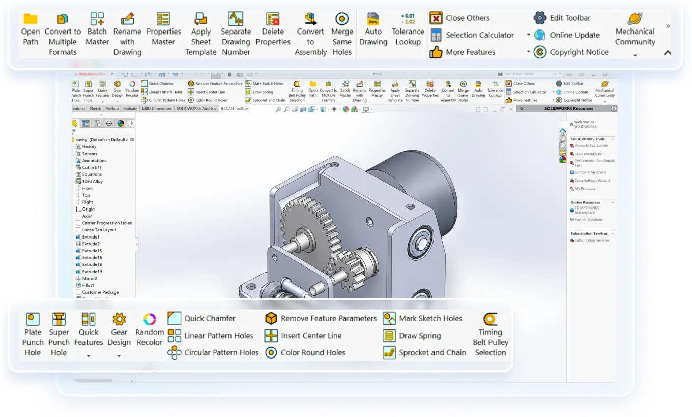
Common Template and Title Block Mistakes
- Saving the template and the sheet format in different folders. The link breaks for every user who does not have your local path.
- Typing part numbers into the title block. The next revision changes the model and not the drawing, and the two disagree.
- Leaving working views in the template. Anything on the sheet when you save the template shows up in every new drawing. Delete test views before saving.
- Forgetting the projection setting. It lives in the sheet properties and template, not the sheet format. A drawing started from the wrong template can be in third angle when the customer expects first.
- Putting the revision table in the sheet format. It will not save there. Add it to the template.
- Making many templates for small differences. One template per sheet size and one sheet format per title block layout is easier to maintain than one per project.
- Changing the title block and forgetting the old drawings. Decide at the time of the change how the existing ones will be updated, and write it down.
FAQ
What is the difference between a sheet format and a drawing template in SolidWorks? The sheet format (.slddrt) holds the border, title block and standard text for a sheet. The drawing template (.drwdot) is the file a new drawing starts from. It stores sheet properties such as projection type, can include predefined views or extra sheets, and links to a sheet format.
Where are SolidWorks drawing templates stored? In the folder defined in File Locations under Document Templates, which defaults to a location inside the SolidWorks installation or program data folder. Because defaults change between versions, most teams set their own shared folder and add it in Options.
Why does my title block show blank fields? Usually one of three reasons. There is no view on the sheet yet for $PRPSHEET to read from, the property name in the note does not match a property on the model, or the sheet points at a different model than you expect. Use View > Annotation Link Variables to find empty linked notes.
Can one drawing have different title blocks? Yes. Each sheet of a drawing can have its own sheet format, for example a full title block on the first sheet and a shorter one on later sheets.
How do I change the template for a drawing I already made? Change the sheet format in the sheet properties by browsing to the new .slddrt. Other template settings, such as projection type, are set in the same dialog or in the document properties.
What does a title block have to include? It depends on your company or customer standard, and most mechanical drawings carry at least an identification number, a title, the owner, revision, scale and sheet number. Our title block guide lists the fields and the standards behind them.
Popular Articles
Keep Learning
Engineering Drawing Examples: Annotated Part, Assembly, Exploded, Weldment and Sheet Metal Drawings
Quick answer: A good engineering drawing example shows more than the views. It shows how the views, dimensions, symbols, notes and title block work together for one specific part. The six examples below cover a machined part, a part with an inclined face, an assembly, an exploded assembly, a welded frame and a sheet metal part, and each one says why it is drawn the way it is. Use them as a pattern for your own drawings, or as exercises. Searching for engineering drawing examples mostly returns picture......
How to Export a SolidWorks Drawing to PDF, DXF and DWG (and Export Many at Once)
Quick answer: To export a SolidWorks drawing to PDF, use File > Save As, choose PDF as the type and set the options for colour, fonts and quality. For DXF or DWG, use File > Export As in newer versions (File > Save As in older ones), choose the type and set the export options, including whether a multi-sheet drawing goes to paper space. Most export problems come from the drawing's display quality, scale and fonts, not from the file type. The drawing is finished and checked, and now someone needs it in......
SolidWorks Weldment Drawing: Views, Cut List, Balloons, and Weld Symbols
Quick answer: A SolidWorks weldment drawing shows a welded frame in a few views of the whole weldment, a cut list that lists each structural member with its length and quantity, balloons tied to that list, and weld symbols that say how each joint is made. Build the views and the Weldment Cut List table from the weldment part, add balloons so their numbers follow the cut list, and bring in or add weld symbols last. The drawing is only as good as the cut list in the part, so check the properties and the......
Drawing Views in SolidWorks: Orthographic, Isometric, Section, Auxiliary, Detail, and Break Views
Quick answer: Drawing views are 2D pictures of a 3D model. Orthographic views (front, top, right) show true shapes and carry the dimensions, an isometric view shows the part's general form, and derived views handle special jobs: section views for the inside, auxiliary views for inclined faces, detail views for small features, and break and crop views for long or crowded views. In SolidWorks, you place a base view first and derive the others from it, which keeps them aligned and linked to their parent.......
SolidWorks Exploded View: Create It, Add Explode Lines, and Show It on a Drawing
Quick answer: An exploded view is built in the assembly, not in the drawing. Click Exploded View, add steps that move components along an axis, add explode lines with Explode Line Sketch, then on the drawing select a model view of the assembly and turn on Show in exploded or model break state. Balloons on that view read from the BOM as usual, and most missing explode lines come down to sketch display or the wrong configuration. The shop gets twelve part drawings and a pile of parts. Nothing says which......
Assembly Drawing vs Detail Drawing in SolidWorks: What Goes on Each, and How to Build the Assembly Drawing
Quick answer: An assembly drawing shows how the parts of a product fit together, with views, a bill of materials and balloons that link each part to its row. A detail drawing shows one part with everything needed to make it. In SolidWorks, you build the assembly drawing from the assembly, add a section view where it helps, insert the BOM and balloons, and add an exploded view when the reader needs the order of assembly (see our exploded view guide). The shop gets twelve part drawings and a pile of par......