SolidWorks Weldment Drawing: Views, Cut List, Balloons, and Weld Symbols
17 min
- What a Weldment Drawing Needs
- Set Up the Weldment Part First
- Views of a Weldment
- The Weldment Cut List
- Balloons on a Weldment
- Weld Symbols
- Weld Beads in the Drawing
- Example: A Welded Frame Drawing Set
- Fixing the Usual Problems
- Where JLCCAN Fits
- Common Weldment Drawing Mistakes
- FAQ
Quick answer: A SolidWorks weldment drawing shows a welded frame in a few views of the whole weldment, a cut list that lists each structural member with its length and quantity, balloons tied to that list, and weld symbols that say how each joint is made. Build the views and the Weldment Cut List table from the weldment part, add balloons so their numbers follow the cut list, and bring in or add weld symbols last. The drawing is only as good as the cut list in the part, so check the properties and the grouping of members there first.
The frame is welded, the drawing is released, and then the fabricator asks why the list shows twelve legs when the design has four, or why every balloon says 1. Or the weld symbols that were on the model never made it to the sheet. None of these is a drawing problem at root. The cut list, the balloons and the weld symbols all read from the weldment part, so most faults are fixed there.
This guide covers what a weldment drawing needs, how to set up the part, how to place views of the whole frame and of a single member, how to insert the cut list and tie balloons to it, how to read and add weld symbols, and how to fix the usual faults. For the general drawing workflow, see our guide to creating a SolidWorks 3D to 2D drawing.
Key Takeaways
- A weldment drawing combines an overall view, views of individual members, a cut list, balloons and weld symbols, and each is set up in a different place.
- Cut list properties are named LENGTH, Angle1 and Angle2, and they cannot be edited, so changes are made in the weldment part and the cut list is updated.
- A relative view with the Scope option shows only the selected bodies of a multibody part, which is how a single member is shown.
- SolidWorks' own Weld Symbol tool adds the symbols, since JLCCAN has no weld symbol function, its Auto-Drawing does not support weldments, and its Advanced BOM does not recognize cut list items.
What a Weldment Drawing Needs
In SolidWorks a weldment is a multibody part made from structural members (tube, angle, channel, plate) joined by welds. Because the members are bodies in one file, the drawing has to explain both the whole frame and the individual pieces a fabricator must cut. "Weldment drawing" here means that drawing. It is not the same as a weld joint detail, which shows only the preparation and size of one joint.
A complete set usually has five parts. The overview views show the frame as a whole, and one or more views of single members show cuts, holes or end preparation. The cut list lists each member once with its profile, length and quantity. Balloons tie each member in the views to its row in the cut list. Weld symbols state the type and size of each weld. Notes cover general weld size, process, and the order of welding or finishing if it matters.
| Part of the drawing | What it answers | Where it comes from |
|---|---|---|
| Overview views | What does the finished frame look like? | The weldment part |
| Single-member views | How is this piece cut and drilled? | A view relative to one body |
| Cut list | What do I cut, and how many? | The cut list folder in the part |
| Balloons | Which row is this piece? | The cut list |
| Weld symbols | How is this joint welded? | Weld features in the model, or added in the drawing |
Set Up the Weldment Part First
The cut list table is built from the cut list folder in the weldment part, so the quality of the table is decided there. SolidWorks groups identical structural members into one cut list item, and each item carries properties such as description, length and, for mitred members, cut angles. The property names are LENGTH, Angle1 and Angle2 (no space), and newer versions add DESCRIPTION, MATERIAL, QUANTITY and TOTAL LENGTH. These properties cannot be edited. Members that differ in profile, length or end condition become separate items, which is correct, but members that should match and do not will show as extra rows.
Before starting the drawing, open the part and check three things. Every member should have the description you want in the table, because empty or default descriptions end up on the sheet. Members that should be identical should sit in the same cut list item, so the quantity is right. And any custom property you plan to show, such as material, finish or part number, should exist on the cut list items. These checks take minutes and save the usual round of corrections later. Our BOM guide covers the same rule for assemblies: the table reads the model, so fix the model.
Views of a Weldment
Start with the overview views. Place a front view and the projected views you need, plus an isometric view of the whole frame, in the usual way (see our drawing views guide). SolidWorks Help says a weldment drawing can show the entire weldment or a single body, so the choice is yours for each view. If the frame is part of a larger assembly, see our assembly drawing guide for the sheet-level view.
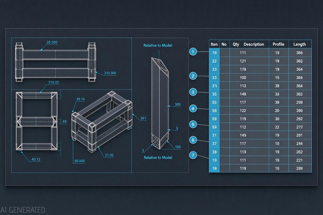
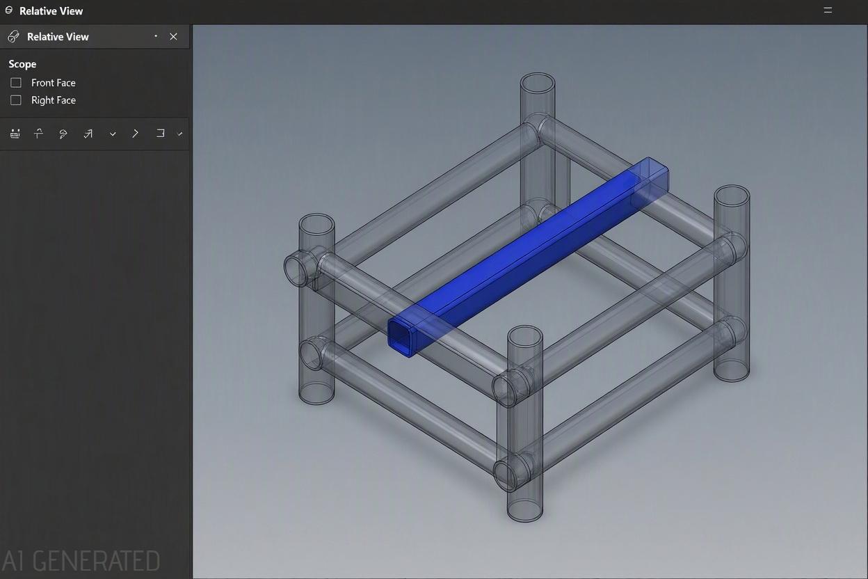
For a single member, insert a view relative to the model. In the drawing, use Insert > Drawing View > Relative to Model, pick two faces of the body to define the orientation, and the view shows the member square on. The command is also on the Drawing toolbar as Relative View, and the two references must be orthogonal faces or planes. For a multibody part such as a weldment, the view shows only the bodies you pick under Scope. This is how you draw a tube with a mitre cut, a plate with holes, or any member that cannot be read from the overview views.
Section views work in the usual way, and in a weldment SolidWorks Help notes that adjacent bodies in a section can be hatched with alternating crosshatch so neighbouring members can be told apart. Use a section where members overlap or where a weld sits inside a joint that the outside views hide.
| View | Use it to show | Tool |
|---|---|---|
| Overview (front, top, isometric) | The finished frame and overall size | Model View, Projected View |
| View of a single member | Cuts, holes and end preparation of one piece | Relative to Model |
| Section | Joints and overlaps hidden from outside | Section View |
| Detail | A small joint or weld enlarged | Detail View |
The Weldment Cut List
The cut list is a table. Choose Insert > Tables > Weldment Cut List, select a view of the weldment, pick a table template and place the table. The command is also on the Table toolbar. The default cut list template has four columns: item number, quantity, description and length. Columns come from the template, and each column reads a property of the cut list items. A typical fabrication layout is item number, quantity, description, profile, length and material.
A few settings matter in practice. If the part changes after the table is placed, the cut list in the part needs to update so the table reflects the change. In the weldment part, right-click the Cut list folder and choose Update. If two items should be one, fix the cause in the part (a difference in profile, length or a property) and combine them there, not in the table. Properties you want in the table, such as material or finish, can be linked to custom properties so they fill in from the model instead of being typed.
There is one thing that confuses people moving between drawing types. A weldment has a cut list, and an assembly has a bill of materials, and they are two different tables built from different sources. If a weldment sits inside an assembly, the assembly BOM can list the weldment as one row or break it into members. SolidWorks Help covers this under dissolving a subassembly or weldment in a BOM, and the BOM PropertyManager has an option to dissolve part-level rows. See our BOM guide for when to use each. A sheet metal part also has a cut list, but the properties come from the bent flat pattern and not from structural members.
Balloons on a Weldment
Balloons read their numbers from the cut list. Use Auto Balloon on the Annotation tab to place balloons on all members in a view at once, and the numbers follow the cut list items. SolidWorks Help says balloon numbers stay associated with the cut list, so if the list changes the balloons follow. If the drawing has no cut list when you run Auto Balloon, SolidWorks asks you to create one first.
Two behaviours cause most of the trouble. If the cut list is deleted from the drawing, the balloon numbers reset to 1, which is why a sheet can suddenly show the same number on every balloon. And a weldment drawing shares one cut list across configurations, so a balloon number does not change between configurations of the same frame.
| Symptom | Likely cause | Fix |
|---|---|---|
| Every balloon shows 1 | The cut list table was deleted | Insert the Weldment Cut List again, then re-link the balloons |
| Auto Balloon asks about a cut list | The drawing has no cut list yet | Create the cut list first, then place balloons |
| Balloon numbers differ from the table | The table is from a different view or model | Check the view the table was built from |
| Two balloons for pieces that should match | The pieces are separate cut list items | Fix the difference in the part and regroup |
Weld Symbols
How to Read a Weld Symbol
A weld symbol is a short code on a drawing that says what kind of weld goes at a joint and how big it is. Its parts are standard. A leader with an arrow points to the joint. A horizontal reference line carries the symbols. The side of the reference line a symbol sits on says which side of the joint is welded: below the line means the arrow side of the joint, above means the other side. The shape of the symbol gives the weld type, such as a triangle for a fillet weld or a V shape for a groove weld. Size goes to the left of the symbol, and length and pitch for an intermittent weld go to the right.
Supplementary marks add more. A circle at the bend of the leader means weld all around, a flag means a field weld (made on site, not in the shop), and a tail on the reference line holds notes such as the process or a specification. Intermittent welds, often called stitch welds, are written as length and pitch, tack welds and spot welds have their own marks, and a bead weld symbol covers a surfacing or back bead.
| Mark | Meaning |
|---|---|
| Triangle | Fillet weld |
| V or bevel shapes | Groove welds |
| Circle at the leader bend | Weld all around |
| Flag | Field weld |
| Length and pitch to the right | Intermittent (stitch) weld |
| Tail | Process, specification or notes Two standards define the symbols, AWS A2.4 and ISO 2553, and they do not draw everything the same way. The ISO system uses a dashed line alongside the reference line to show the other side, where the AWS system uses the position above or below the line. Pick the standard your customer specifies and keep to it on the whole drawing. |
Add Weld Symbols in SolidWorks
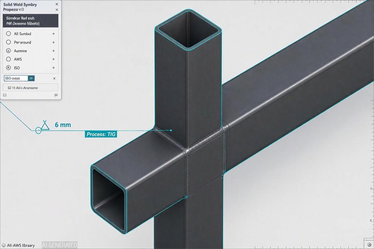
SolidWorks has a Weld Symbol tool that places weld symbols in assemblies, in drawings and on edges, faces and vertices of parts. The symbol libraries cover ANSI, ISO, GOST and JIS, so you can match the standard above. The tool is on the Annotation tab, or under Insert > Annotations > Weld Symbol. For how weld symbols sit among the other drawing symbols, see our guide to drawing standards.
There are two routes. When you create a weld bead in an assembly, or a fillet bead on a weldment structure, SolidWorks creates a weld symbol for it automatically, and symbols made in the model can be brought into the drawing with Model Items. Or you can create the symbol in the drawing itself and attach it to the joint. Model-based symbols keep the weld data in one place, so if the weld changes in the model the drawing can show the new value. Drawing-only symbols are quicker but are a second copy to maintain.
When creating or editing a symbol, SolidWorks lets you add secondary weld information for some types (square or bevel, for example), choose to have no leader anchor, and set the text font. Use multi jog leader gives one leader several bends, and Include this symbol in weld table adds the symbol to a weld table. If symbols that exist in the model do not appear in the drawing, check the Model Items import options first. Users report that importing weld symbols this way does not always succeed.
Weld Beads in the Drawing
Weld symbols describe the weld, and a weld bead is the 3D feature that shows it in the model. These are two separate things, and people often search for the second when they want the first. A weld bead in an assembly is a feature that adds the weld geometry between components, and a fillet bead on a weldment structure does the same inside the part. If the bead is missing from the drawing view, check that the feature exists in the model and is not suppressed or hidden, that the view shows the configuration or component that contains it, and that the view's display settings do not hide it.
For most fabrication drawings, the weld symbol is what the welder reads, and the bead geometry is a visual aid. Decide which one the drawing needs before spending time on the other.
Example: A Welded Frame Drawing Set
Here is the example for the rest of this guide. It is a small equipment stand made of 40 × 40 × 3 mm square tube, 600 mm long and 400 mm wide overall: four legs, two long rails, two short rails, four corner gussets and four foot caps. The dimensions are invented for the example.
| Item | Description | Profile | Length (mm) | Qty |
|---|---|---|---|---|
| 1 | Leg | Square tube 40 × 40 × 3 | 500 | 4 |
| 2 | Long rail | Square tube 40 × 40 × 3 | 520 | 2 |
| 3 | Short rail | Square tube 40 × 40 × 3 | 320 | 2 |
| 4 | Corner gusset | Plate 3 mm | n/a | 4 |
| 5 | Foot cap | Plate 3 mm | n/a | 4 The rails are 520 and 320 because they fit between the legs: 600 minus two 40 mm legs, and 400 minus two. The sheets are planned like this. |
| Sheet | Contents |
|---|---|
| 1 | Front, top and isometric views of the whole frame, the cut list and balloons, overall dimensions, general weld note |
| 2 | One view of a leg and one view of a rail, each relative to the model, showing cuts and holes |
| 3 | Detail views of the gusset joint and the foot cap, with weld symbols Sheet 1 answers what to cut and how many. Sheet 2 answers how a single piece is made. Sheet 3 answers how the joints are welded. A fabricator can work from the first sheet alone for a simple frame, and the other two matter when the pieces or joints need more than a line of text. |
Fixing the Usual Problems
| Symptom | What to check |
|---|---|
| Cut list is empty | The part has no cut list items, or the table was built from a view of a different model |
| Too many rows for the same member | The members differ in profile, length or a property, so they are not grouped |
| Cut list does not match the BOM | The assembly BOM lists the weldment as one row, or the BOM and the cut list are being compared as if they were one table |
| All balloons show 1 | The cut list table was deleted from the drawing |
| Balloon numbers differ between sheets | Tables built from different views or models |
| Weld symbols missing in the drawing | Model Items import options, or the symbols were created in another document |
| Weld bead not visible in a view | The bead is suppressed, hidden, or the view does not show the component or configuration that holds it |
| Section hatch makes members hard to tell apart | Use alternating crosshatch so neighbouring bodies differ |
Where JLCCAN Fits
Weldment drawings repeat the same chores on every frame: filling in properties, checking descriptions, producing the same table layout. JLCCAN's features page lists tools that work on part properties and BOM data, including Property Manager and Part Number Parsing under BOM & Data Tools, Batch Manager for batch property editing across files, and Advanced BOM for assembly BOM structures. JLCCAN also has a frame design module, which its changelog describes as an aluminium extrusion frame tool, so it covers extrusion frames and not the welded steel frames this guide deals with.
According to JLCCAN's product team, Auto-Drawing does not support weldment parts, Advanced BOM does not recognise cut list items, and there is no tool for weld symbols. The cut list, the balloons and the weld symbols in this guide are therefore all set up in SolidWorks itself, and the JLCCAN tools above only help with the properties on the parts before you start.
JLCCAN Auto-Drawing generates standard views and dimension chains straight from your SolidWorks parts, so you can spend your time on engineering review, not repetitive setup
Free Download >
Common Weldment Drawing Mistakes
- Building the cut list table before the part is ready. Empty descriptions and extra rows come from the part, not the table.
- Fixing a quantity in the table. Regroup the members in the part instead, so the table and the model agree.
- Deleting the cut list and re-inserting it blindly. Balloons reset to 1 and have to be relinked.
- Treating the BOM and the cut list as one table. They have different sources.
- Drawing every member in the overview and nothing relative. The fabricator then has no view that shows a cut or hole square on.
- Typing weld symbols that exist in the model. Bring them in with Model Items so they stay in step.
- Mixing AWS and ISO symbol conventions on one drawing. Pick the one the customer specifies.
- Adding weld bead geometry when the weld symbol is enough. Choose the one the shop needs.
FAQ
What is a weldment drawing? In SolidWorks, a drawing of a welded frame made of structural members, with overview views, views of single members, a cut list, balloons and weld symbols. It is different from a weld joint detail, which covers one joint.
How do I make a weldment drawing in SolidWorks? Start a drawing from the weldment part, place the overview views, add views of single members with Relative to Model, insert the Weldment Cut List, add balloons with Auto Balloon, and bring in or add the weld symbols.
How do I add a cut list to a SolidWorks drawing? Use Insert > Tables > Weldment Cut List, select a view of the weldment, choose a template and place the table. The table reads the cut list in the part.
Why do all my balloons show 1? Usually because the cut list table was deleted from the drawing. Insert the Weldment Cut List again and relink the balloons.
How do I show weld symbols in a SolidWorks drawing? Weld symbols made in the model can be imported with Model Items, and you can also create them in the drawing with the Weld Symbol tool, using the ANSI, ISO, GOST or JIS library.
Do sheet metal parts have a cut list too? Yes, but its properties come from the sheet metal flat pattern and not from structural members, so the settings and columns differ from a weldment cut list.
Popular Articles
Keep Learning
Engineering Drawing Examples: Annotated Part, Assembly, Exploded, Weldment and Sheet Metal Drawings
Quick answer: A good engineering drawing example shows more than the views. It shows how the views, dimensions, symbols, notes and title block work together for one specific part. The six examples below cover a machined part, a part with an inclined face, an assembly, an exploded assembly, a welded frame and a sheet metal part, and each one says why it is drawn the way it is. Use them as a pattern for your own drawings, or as exercises. Searching for engineering drawing examples mostly returns picture......
How to Export a SolidWorks Drawing to PDF, DXF and DWG (and Export Many at Once)
Quick answer: To export a SolidWorks drawing to PDF, use File > Save As, choose PDF as the type and set the options for colour, fonts and quality. For DXF or DWG, use File > Export As in newer versions (File > Save As in older ones), choose the type and set the export options, including whether a multi-sheet drawing goes to paper space. Most export problems come from the drawing's display quality, scale and fonts, not from the file type. The drawing is finished and checked, and now someone needs it in......
SolidWorks Weldment Drawing: Views, Cut List, Balloons, and Weld Symbols
Quick answer: A SolidWorks weldment drawing shows a welded frame in a few views of the whole weldment, a cut list that lists each structural member with its length and quantity, balloons tied to that list, and weld symbols that say how each joint is made. Build the views and the Weldment Cut List table from the weldment part, add balloons so their numbers follow the cut list, and bring in or add weld symbols last. The drawing is only as good as the cut list in the part, so check the properties and the......
Drawing Views in SolidWorks: Orthographic, Isometric, Section, Auxiliary, Detail, and Break Views
Quick answer: Drawing views are 2D pictures of a 3D model. Orthographic views (front, top, right) show true shapes and carry the dimensions, an isometric view shows the part's general form, and derived views handle special jobs: section views for the inside, auxiliary views for inclined faces, detail views for small features, and break and crop views for long or crowded views. In SolidWorks, you place a base view first and derive the others from it, which keeps them aligned and linked to their parent.......
SolidWorks Exploded View: Create It, Add Explode Lines, and Show It on a Drawing
Quick answer: An exploded view is built in the assembly, not in the drawing. Click Exploded View, add steps that move components along an axis, add explode lines with Explode Line Sketch, then on the drawing select a model view of the assembly and turn on Show in exploded or model break state. Balloons on that view read from the BOM as usual, and most missing explode lines come down to sketch display or the wrong configuration. The shop gets twelve part drawings and a pile of parts. Nothing says which......
Assembly Drawing vs Detail Drawing in SolidWorks: What Goes on Each, and How to Build the Assembly Drawing
Quick answer: An assembly drawing shows how the parts of a product fit together, with views, a bill of materials and balloons that link each part to its row. A detail drawing shows one part with everything needed to make it. In SolidWorks, you build the assembly drawing from the assembly, add a section view where it helps, insert the BOM and balloons, and add an exploded view when the reader needs the order of assembly (see our exploded view guide). The shop gets twelve part drawings and a pile of par......