Bill of Materials in SolidWorks: How to Create, Structure, and Export One (With Example)
15 min
- What a Bill of Materials Contains
- Parts List vs Bill of Materials
- Three BOM Types, One Assembly
- How to Create a Bill of Materials
- Set Up the Model So the BOM Comes Out Right
- Balloons and Item Numbers
- Exporting to Excel
- Fixing the Usual BOM Problems
- Where JLCCAN Fits
- Common Bill of Materials Mistakes
- FAQ
Quick answer: In SolidWorks, a bill of materials (BOM) is a table that lists an assembly's components with item numbers, part numbers, descriptions and quantities, inserted from Insert > Tables > Bill of Materials. Choose the BOM type (Top-level only, Parts only or Indented) by who will read the drawing, and fill in the properties on your parts first, because the table and the balloons both read from the model. Export the table to Excel when purchasing or production needs a spreadsheet.
The drawing is finished, the balloons are placed, and then purchasing asks why the bill of materials lists twelve screws when the assembly has sixteen. Or a balloon shows an asterisk instead of a number. Or the part numbers in the table do not match the ones in the title blocks.
Both the table and the balloons read from the model, so these are model problems more than table problems. This guide covers what a BOM contains, how a parts list differs from it, the three BOM types SolidWorks offers (with the same assembly shown in each), how to create one, how to keep balloons and item numbers in step, and how to export to Excel. It ends with a checklist for the usual faults. For the rest of the drawing workflow, see our guide to creating a SolidWorks 3D to 2D drawing.
Key Takeaways
- The BOM is built from the assembly structure, and the type you choose (top-level only, parts only or indented) decides what the reader of the drawing sees.
- A component excluded from the BOM shows an asterisk in its balloon, and overwriting a value that SolidWorks supplies breaks the link between that cell and the model data.
- A table-based BOM is exported by right-clicking the table and choosing Save As, and an Excel-based BOM is saved with File > Save As and no longer stays linked to the drawing.
- JLCCAN's Advanced BOM writes edited properties back to the part files and works alongside the SolidWorks BOM, but it does not recognize weldment cut lists.
What a Bill of Materials Contains
A bill of materials lists the parts, subassemblies and hardware needed to build an assembly, with the quantity of each. On an engineering drawing it is a table next to the title block, and each row is tied to a balloon on the views. Engineering teams also split the idea in two: an engineering BOM follows the design structure, and a manufacturing BOM follows how the product is built and bought.
Here is the example used in the rest of this guide. It is a small mounting assembly: a base plate, a bracket, a clamp subassembly (a clamp arm and two M5 screws), four M6 screws with washers, and two dowel pins.
| Item | Part number | Description | Material | Qty |
|---|---|---|---|---|
| 1 | MB-1001 | Base plate, 120 × 80 × 10 | Steel S355 | 1 |
| 2 | MB-1002 | Bracket | Aluminium 6061 | 1 |
| 3 | MB-2000 | Clamp subassembly | n/a | 1 |
| 4 | ISO 4762 M6×16 | Socket head cap screw | Steel 8.8 | 4 |
| 5 | ISO 7089 M6 | Washer | Steel | 4 |
| 6 | ISO 2338 6×20 | Dowel pin | Steel | 2 The part numbers and materials above are invented for the example. What matters is where each column comes from in SolidWorks. |
| Column | Source in SolidWorks | If it is empty |
|---|---|---|
| Item No. | Generated by the BOM, follows assembly order unless locked | Check the item number settings |
| Part number | A custom property, or the file or configuration name | Add the property to the part |
| Description | Custom property "Description" | Add it to the part or part template |
| Material | Custom property or the material assigned to the part | Assign a material, or link the property |
| Qty | Counted from the assembly | Check whether a component is excluded The lesson is in the right-hand column. Almost every empty cell in a BOM traces back to a property that was never set on the model. |
Parts List vs Bill of Materials
Search for "parts list" on its own and the results are rarely about drawings. They come from logistics glossaries, from aftermarket parts catalogues where each row is something a customer can order, and from ERP documentation. On a SolidWorks drawing the question is simpler: the table most people call a parts list is the bill of materials table, and SolidWorks inserts it as a Bill of Materials.
What differs is how much structure the reader wants. A flat list of every loose part to buy is what the Parts only type produces, while a list that keeps subassemblies visible is Top-level only or Indented (the next section shows all three). A welded frame adds a cut list on top of this, which has its own table and settings and is covered in our weldment drawing guide.
Three BOM Types, One Assembly
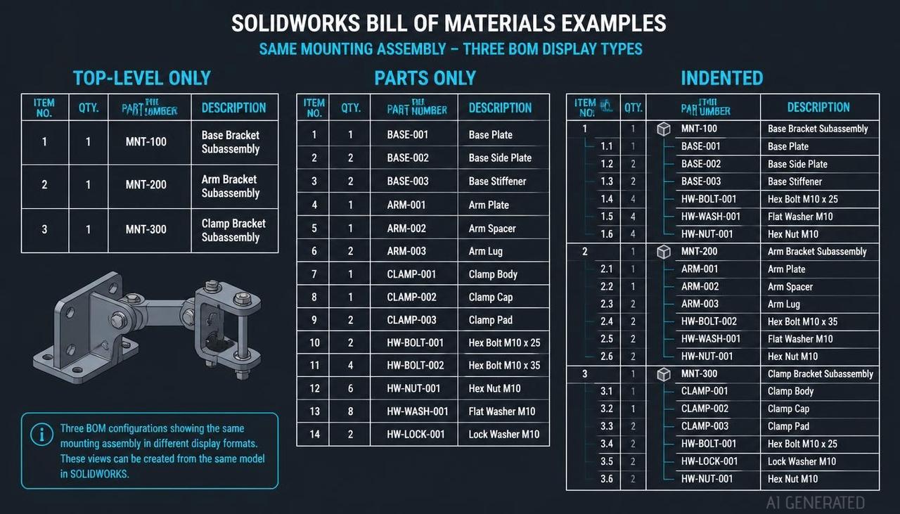
When you insert a BOM, SolidWorks asks for a BOM type. The type decides which rows appear, and it is the most common reason a table does not match what someone expected. Here are the three types applied to the example assembly, with the Help definition of each.
- Top-level only lists parts and subassemblies, but not the components inside the subassemblies.
- Parts only lists the subassembly components as individual items and does not list the subassembly itself.
- Indented lists the subassembly and, under it, its components.
| Row | Top-level only | Parts only | Indented |
|---|---|---|---|
| Base plate | 1 | 1 | 1 |
| Bracket | 1 | 1 | 1 |
| Clamp subassembly | 1 | not listed | 1 |
| Clamp arm | not listed | 1 | 1, indented under the subassembly |
| M5 screw | not listed | 2 | 2, indented under the subassembly |
| M6 screw | 4 | 4 | 4 |
| M6 washer | 4 | 4 | 4 |
| Dowel pin | 2 | 2 | 2 |
| Total rows | 6 | 7 | 8 Which one is right depends on who reads it. |
- Top-level only suits an assembly drawing where the clamp subassembly has its own drawing and BOM. The reader sees what to buy or build at this level.
- Parts only suits purchasing and kitting, where nobody cares about the subassembly as an object and only needs a total of every loose part.
- Indented suits a single drawing that has to show the whole structure. It is also the closest to a multi-level BOM, the form manufacturing systems expect.
- Two practical points. First, SolidWorks Help warns that changing the BOM type of an existing BOM increases the file size and may slow performance, so the cleaner route is to delete the table and insert a new one with the type you need. Second, you can dissolve a subassembly in a BOM when you want its components listed in the parent, which is quicker than rebuilding the structure. Click the left side of the table to show the assembly structure column if it is hidden, right-click the subassembly cells in that column and choose Dissolve. To undo it, right-click a cell marked as dissolved and choose Restore Restructured Components.
How to Create a Bill of Materials
You can create a BOM in a drawing, or in an assembly (and in multibody part files) without making a drawing first.
- Fill in the properties first. Part number, description and material on every part, plus the subassemblies. See the next section.
- Open the tool. In the drawing, click Bill of Materials on the Table toolbar or use Insert > Tables > Bill of Materials, then click an assembly view.
- Choose the template. The columns of the BOM match the table template you pick. Standard templates come with SolidWorks, and you can make your own.
- Choose the BOM type. Top-level only, Parts only or Indented, as above.
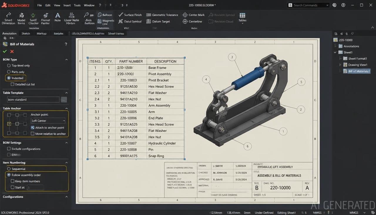
- Set the table position and item numbers. Pick the anchor (top left or top right) and the starting number. "Follow assembly order" orders item numbers like the assembly tree. "Do not change item numbers" locks them, which stops numbers shifting when someone edits the assembly.
- Check the quantities, especially if the assembly has configurations. SolidWorks can list quantities for all selected configurations.
- Document Properties > Tables > Bill of Materials holds the defaults for the active document, so set them once in your drawing template (see our drawing template guide).
Set Up the Model So the BOM Comes Out Right
A BOM reads data from the components, so most of the effort belongs there, not in the table.
- Put the BOM properties in the part and assembly templates. Part number, description, material, finish, supplier. A new part then starts with the right empty fields instead of none.
- Exclude what does not belong. In the assembly, right-click a component, choose Component Properties and select Exclude from bill of materials. Use it for reference geometry, fixtures or cosmetic parts that are not built or bought.
- Combine like items. Identical components appear as one row with a quantity. If two screws that are identical show as two rows, they differ in a property (often the configuration name or a description), and fixing that is what combines them.
- Show one item number across configurations. If the same component appears in two top-level configurations, the option to display it as one item number keeps the number the same. SolidWorks Help says to use it with Top-level only.
- Name configurations deliberately. The part number shown in the BOM can use the configuration name, so careless names end up in the table.
- Be careful when you edit a cell by hand. SolidWorks Help says that overwriting a value that SolidWorks supplies, such as Item Number or Quantity, breaks the link between the data and the BOM. Change the property on the part instead and the table updates.
Balloons and Item Numbers
Balloons in a drawing read their numbers from the BOM. If the drawing has no BOM yet, balloons use the numbers the software would assign if you inserted one. A balloon can show the item number, the quantity or a custom property.
Auto Balloon (Annotation tab) places balloons on all components in a view at once. Three behaviours cause most of the problems.
| Symptom | Cause | Fix |
|---|---|---|
| A balloon shows an asterisk | The component is set to Exclude from bill of materials, so it has no item number | Clear the exclusion, or decide that the part should not be ballooned |
| Balloon numbers do not match the table | The view is linked to a different table, or the component is not in the configuration shown in the BOM | In the drawing view properties, link the balloon text to the right table, and check the configuration |
| Changing a balloon number does nothing, or the table changes too | Item numbers are locked, or the BOM follows assembly order | Clear Do not change item numbers in the BOM, change the number, and decide whether to lock it again A related point: changing the item number in a balloon changes it in the BOM too, because they are the same data. A reviewer who "fixes" a balloon is editing the table. For an asterisk caused by a subassembly's hidden components, SolidWorks resellers point to the configuration option for how child components display when the subassembly is used in a higher-level assembly. Check that setting before you change every part. |
Exporting to Excel
SolidWorks has two kinds of BOM, and a drawing can hold one or the other, not both.
| Table-based BOM | Excel-based BOM | |
|---|---|---|
| Built on | SolidWorks tables, with templates and anchors | An embedded Excel sheet |
| Item number changes | Clear Do not change item numbers | Clear Row numbers follow assembly ordering on the Control tab |
| Best for | Most drawings | Teams that already format the BOM with Excel formulas and styles Most teams use the table-based BOM and export it when they need a spreadsheet. For a table-based BOM, right-click the table and choose Save As. The file types include Excel (.xls or .xlsx, with an option to include thumbnails), CSV, text, a table template (.sldbomtbt), DXF, DWG and eDrawings. For an Excel-based BOM the route is documented: click the table on the drawing sheet, choose File > Save As, name the file and save. The saved file is not linked to the BOM in the drawing, so edits to one do not affect the other. A clean export needs the right columns. A typical manufacturing layout is: |
| Item No. | Part number | Description | Material | Qty | Supplier | Unit cost | Notes |
|---|---|---|---|---|---|---|---|
| 1 | MB-1001 | Base plate | Steel S355 | 1 | In-house | Machined | |
| 4 | ISO 4762 M6×16 | Socket head cap screw | Steel 8.8 | 4 | Stock | Keep the first three columns identical in the drawing and the spreadsheet, and let purchasing add the columns SolidWorks does not know about (supplier, cost, lead time) in the spreadsheet only. |
Fixing the Usual BOM Problems
| Symptom | What to check |
|---|---|
| Quantity too low | A component is excluded, or two identical parts differ in a property and were not combined. Check Component Properties and the shared properties |
| Subassembly components missing | The BOM type is Top-level only. Insert an Indented or Parts only BOM |
| Duplicate rows for the same part | The parts differ in configuration name or a property, so they are not treated as like items |
| Empty description or material | The property is missing on the part. Add it to the part or the part template |
| Table changes when the assembly is edited | Item numbers follow assembly order. Lock them if the drawing is released |
| Hardware count does not match the real build | Fasteners were added by patterns or at the wrong level. Count the instances in the assembly tree |
| Weldment items listed oddly | Weldments have their own cut list options, including Dissolve part level rows in the BOM PropertyManager. See the weldment drawing guide |
Where JLCCAN Fits
BOM work is repeated for every assembly, so it suits a plugin. JLCCAN's features page lists these relevant tools:
- Advanced BOM manages assembly BOM structures, part properties and part number rules in one place. It supports flat BOMs, hierarchical BOMs, bulk editing and Excel export.
- Property Manager and Part Number Parsing appear under BOM & Data Tools, along with a tool for deleting properties.
- Batch Manager supports batch renaming, property editing and part number parsing across files.
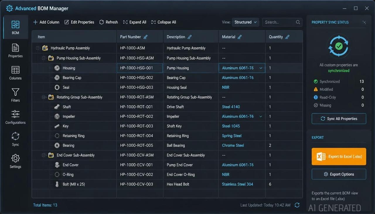
- According to JLCCAN's product team, edits made in Advanced BOM are written back to the part files. It works alongside SolidWorks' own BOM table and does not replace it, and it can read the Exclude from bill of materials setting, but you have to turn that on yourself. The Excel export follows the column headings you set. Part number rules are your own naming convention, not something JLCCAN defines for you.
- The model-side work in this guide still applies, because a tool can only organize the data your parts carry. What a plugin takes over is the repeated editing across many parts, such as filling the same property in fifty files.
JLCCAN Auto-Drawing generates standard views and dimension chains straight from your SolidWorks parts, so you can spend your time on engineering review, not repetitive setup
Free Download >
Common Bill of Materials Mistakes
- Editing cells instead of properties. The change disappears or breaks the link. Edit the property on the part.
- Choosing the BOM type by habit. A Top-level only BOM on a drawing that needs every part gives short counts and no error.
- Excluding a component and forgetting its balloon. The balloon shows an asterisk, which looks like a bug and is a setting.
- Leaving item numbers to follow assembly order on a released drawing. One new component and every number below it shifts.
- Different descriptions for the same part. Two spellings produce two rows.
- Putting supplier and cost in the model. Fine for some teams, but the data usually belongs in the ERP or the spreadsheet, and copying it into every part creates upkeep.
- Changing the type of an existing BOM. SolidWorks Help warns about file size and performance; delete the table and insert a new one instead.
FAQ
What is a bill of materials in SolidWorks? It is a table, in a drawing or an assembly, that lists the components of an assembly with item numbers, part numbers, descriptions and quantities, taken from the model's properties.
How do I add a bill of materials to a SolidWorks drawing? Open the drawing with an assembly view, click Bill of Materials on the Table toolbar or use Insert > Tables > Bill of Materials, select a view, choose a template and a BOM type, and place the table.
Is a parts list the same as a bill of materials? On a drawing, the table called a parts list is the bill of materials table. Outside drawings the term often means a catalogue of orderable parts, which is a different thing.
How do I exclude a component from the BOM? In the assembly, right-click the component, open Component Properties and select Exclude from bill of materials. A balloon on that component then shows an asterisk.
What is the difference between Top-level only, Parts only and Indented? Top-level only lists parts and subassemblies but not the components inside them. Parts only lists the subassembly components as individual items and leaves out the subassembly. Indented lists the subassembly with its components under it.
How do I export a bill of materials from SolidWorks to Excel? For a table-based BOM, right-click the table, choose Save As and pick Excel or CSV as the file type. An Excel-based BOM is saved with File > Save As after selecting the table, and the saved file is not linked to the drawing.
Why do my balloon numbers not match the BOM? Usually the balloon is linked to a different table, the component is not in the configuration shown in the BOM, or item numbers were changed in one place. Link the balloon text to the correct table and check the configuration.
Popular Articles
Keep Learning
Engineering Drawing Examples: Annotated Part, Assembly, Exploded, Weldment and Sheet Metal Drawings
Quick answer: A good engineering drawing example shows more than the views. It shows how the views, dimensions, symbols, notes and title block work together for one specific part. The six examples below cover a machined part, a part with an inclined face, an assembly, an exploded assembly, a welded frame and a sheet metal part, and each one says why it is drawn the way it is. Use them as a pattern for your own drawings, or as exercises. Searching for engineering drawing examples mostly returns picture......
How to Export a SolidWorks Drawing to PDF, DXF and DWG (and Export Many at Once)
Quick answer: To export a SolidWorks drawing to PDF, use File > Save As, choose PDF as the type and set the options for colour, fonts and quality. For DXF or DWG, use File > Export As in newer versions (File > Save As in older ones), choose the type and set the export options, including whether a multi-sheet drawing goes to paper space. Most export problems come from the drawing's display quality, scale and fonts, not from the file type. The drawing is finished and checked, and now someone needs it in......
SolidWorks Weldment Drawing: Views, Cut List, Balloons, and Weld Symbols
Quick answer: A SolidWorks weldment drawing shows a welded frame in a few views of the whole weldment, a cut list that lists each structural member with its length and quantity, balloons tied to that list, and weld symbols that say how each joint is made. Build the views and the Weldment Cut List table from the weldment part, add balloons so their numbers follow the cut list, and bring in or add weld symbols last. The drawing is only as good as the cut list in the part, so check the properties and the......
Drawing Views in SolidWorks: Orthographic, Isometric, Section, Auxiliary, Detail, and Break Views
Quick answer: Drawing views are 2D pictures of a 3D model. Orthographic views (front, top, right) show true shapes and carry the dimensions, an isometric view shows the part's general form, and derived views handle special jobs: section views for the inside, auxiliary views for inclined faces, detail views for small features, and break and crop views for long or crowded views. In SolidWorks, you place a base view first and derive the others from it, which keeps them aligned and linked to their parent.......
SolidWorks Exploded View: Create It, Add Explode Lines, and Show It on a Drawing
Quick answer: An exploded view is built in the assembly, not in the drawing. Click Exploded View, add steps that move components along an axis, add explode lines with Explode Line Sketch, then on the drawing select a model view of the assembly and turn on Show in exploded or model break state. Balloons on that view read from the BOM as usual, and most missing explode lines come down to sketch display or the wrong configuration. The shop gets twelve part drawings and a pile of parts. Nothing says which......
Assembly Drawing vs Detail Drawing in SolidWorks: What Goes on Each, and How to Build the Assembly Drawing
Quick answer: An assembly drawing shows how the parts of a product fit together, with views, a bill of materials and balloons that link each part to its row. A detail drawing shows one part with everything needed to make it. In SolidWorks, you build the assembly drawing from the assembly, add a section view where it helps, insert the BOM and balloons, and add an exploded view when the reader needs the order of assembly (see our exploded view guide). The shop gets twelve part drawings and a pile of par......