SolidWorks Exploded View: Create It, Add Explode Lines, and Show It on a Drawing
12 min
- Where Exploded Views Live
- Create an Exploded View
- Explode Lines
- Edit and Reuse Exploded Views
- Show the Exploded View in a Drawing
- Balloons and BOM on the Exploded View
- Why Explode Lines Don't Show
- Multibody Parts and Exploded Views
- Example: The Mounting Assembly
- Where JLCCAN Fits
- Common Exploded View Mistakes
- FAQ
Quick answer: An exploded view is built in the assembly, not in the drawing. Click Exploded View, add steps that move components along an axis, add explode lines with Explode Line Sketch, then on the drawing select a model view of the assembly and turn on Show in exploded or model break state. Balloons on that view read from the BOM as usual, and most missing explode lines come down to sketch display or the wrong configuration.
The shop gets twelve part drawings and a pile of parts. Nothing says which screw goes where, in what order, or how the clamp fits on the bracket. An exploded view is the picture that answers it, and it is also the picture that most often goes wrong on the drawing: the dashed lines are missing, the balloons say 1, or the view shows the collapsed assembly.
This guide covers where exploded views live, how to create and edit one, how to add explode lines, how to show the view on a drawing, how to keep balloons and the BOM in step, why explode lines do not show, and what to do with a multibody part. For the drawing around it, see our assembly drawing guide.
Key Takeaways
- An exploded view is created in its own configuration, and the drawing shows it through the view's Show in exploded or model break state option, Show in Exploded State, or a reference configuration.
- Explode lines are a 3D sketch made with Explode Line Sketch and Route Line, and Smart Explode Lines, added in SolidWorks 2018, places them automatically.
- A multibody part can be exploded in the part itself, without Smart Explode Lines, body rotation or radial steps, or converted to an assembly with Save Bodies.
- Convert Multibody to Assembly keeps body names and positions but not properties, and JLCCAN has no tool that generates exploded views or explode lines.
Where Exploded Views Live
An exploded view belongs to the assembly, and it is stored with a configuration. That has two consequences. You make it in the assembly document, never in the drawing, so a messy assembly gives a messy exploded view. And the drawing can only show it if the drawing view points at the configuration that contains it. SolidWorks Help recommends creating a new configuration for it before you start, so the collapsed assembly stays untouched.
SolidWorks Help says each configuration can have more than one exploded view, and you can copy an exploded view to another configuration by dragging it in the ConfigurationManager.
Create an Exploded View
Open the assembly and click Exploded View on the Assembly tab, or use Insert > Exploded View.
- Choose the step type. A regular step moves components by translating (and rotating) them along a direction. A radial step moves components outward around an axis, which suits parts around a shaft or a bolt circle.
- Select the components that move in this step. You can pick several at once, such as all four screws.
- Drag along the triad to set the direction and distance. Auto-space components spreads a group of components equally along an axis as you drag, and a slider adjusts the distance between them. Since SolidWorks 2020 you can also turn it on for existing explode steps and pick the center, back or front of the bounding box as the ordering.
- Click Add Step. Each step is one movement of one or more components, and the steps are listed in the PropertyManager. You can roll an explode step back and forward to check the order.
- Click Done when every component has been placed.
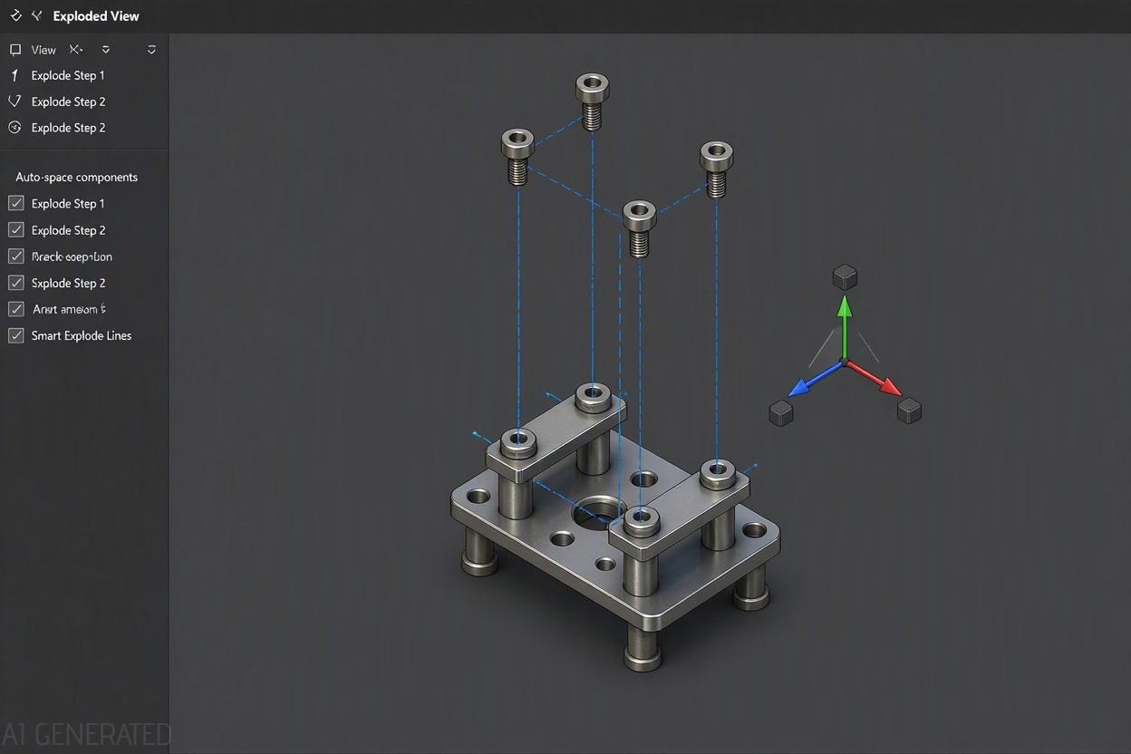
- The order of the steps is the order of assembly read backwards. The part that goes in last comes out first, which is why fasteners usually have the first steps. SolidWorks does not generate a complete explosion by itself. Auto-space and Smart Explode Lines save clicks, but you still decide the direction and sequence.
Explode Lines
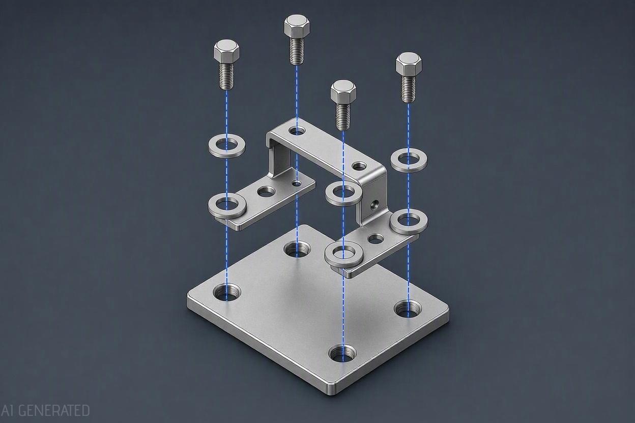
Explode lines are the dashed lines that show where each part came from. They are added with Explode Line Sketch (Insert > Explode Line Sketch), which is a type of 3D sketch. Use the Route Line tool to draw a line between the components, and you can edit the sketch later to add, delete or change lines. Explode Line Sketch is also on the Assembly toolbar, and Jog Line works alongside Route Line. SolidWorks 2018 added Smart Explode Lines (right-click the ExplView feature in the ConfigurationManager and choose Smart Explode Lines), which place lines for you, and the lines can be edited afterwards.
This matters for the drawing. Because the explode lines are a 3D sketch, the drawing treats them like a sketch. If a line is missing from the drawing, it is usually a sketch display problem and not an exploded view problem (see our guide to lines in drawings).
Edit and Reuse Exploded Views
To change an exploded view, edit the exploded view feature in the ConfigurationManager and change, delete or reorder steps. To change the explode lines, edit the explode line sketch.
Exploded views reuse. If a sub-assembly has its own exploded view, you can include it in the parent as a single step, though it is reused as one step, its individual steps are not visible in the parent, and it does not animate there. If a parent shows nested sub-assemblies exploded as one block, expand the steps in the parent or explode the sub-assembly separately.
Show the Exploded View in a Drawing
SolidWorks Help describes the route in three parts. In the assembly, create a new configuration and make the exploded view in it. In the drawing, insert a model view of the assembly in the orientation you need, which is usually isometric. Then right-click the drawing view and choose Properties, and under Configuration information select Show in exploded or model break state. As alternatives, right-click the view and choose Show in Exploded State, or select the option under Reference Configuration in the Drawing View PropertyManager.
You can also drag an Isometric Exploded view from the View Palette when the assembly has an exploded view.
Balloons and BOM on the Exploded View
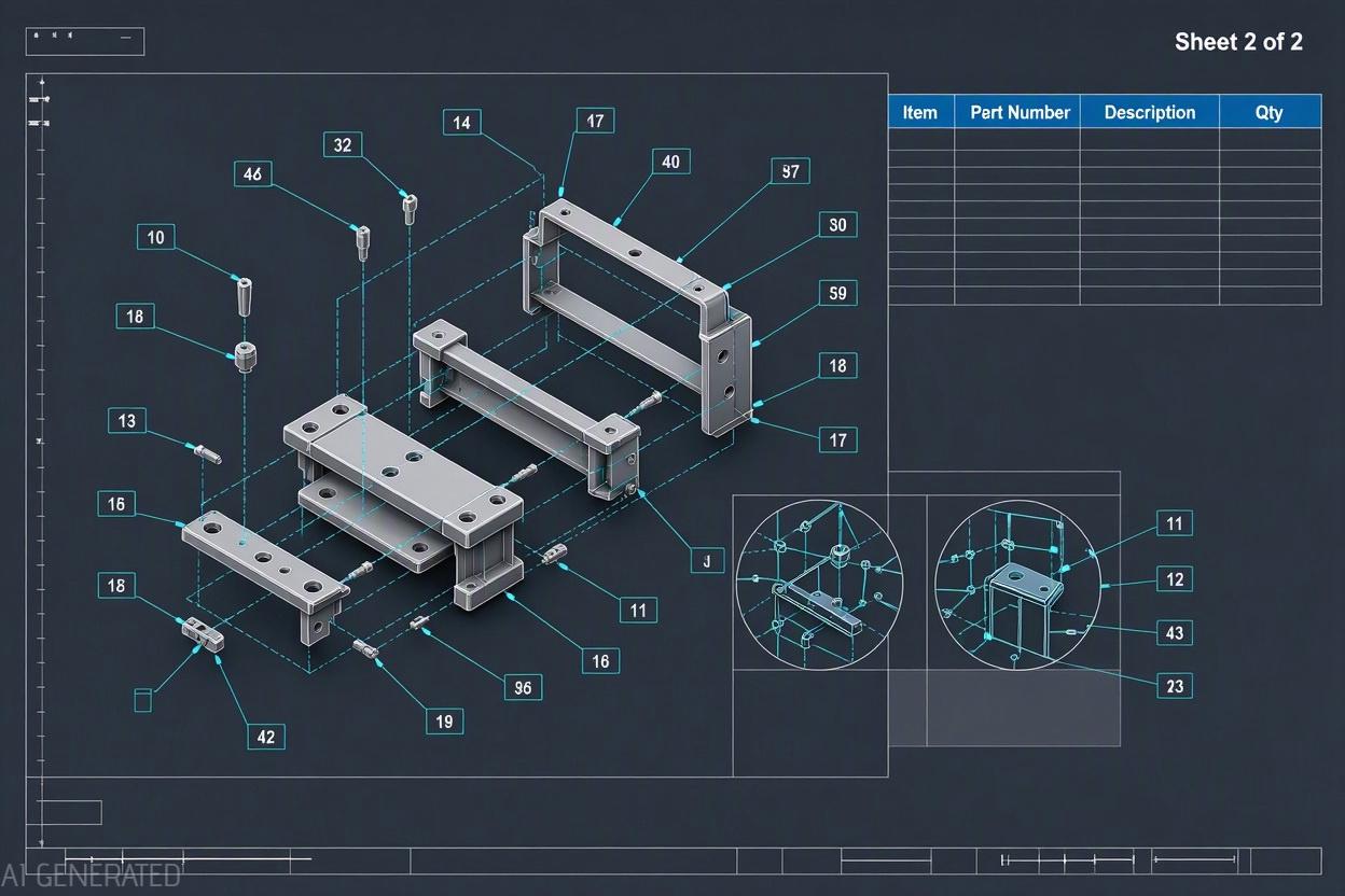
Once the view is exploded, add balloons with Auto Balloon on the Annotation tab. Their numbers follow the BOM, so check them against the table. Components set to Exclude from bill of materials show an asterisk instead of a number.
Decide the BOM type before placing balloons. A Parts only BOM suits an exploded sheet, because every loose part gets its own number and the sub-assembly itself is not listed. SolidWorks Help warns that changing the type of an existing BOM increases file size and may slow performance, so if the type has to change, delete the table and insert a new one. Our BOM guide covers the three types in detail.
For a large assembly, put the exploded view on its own sheet and keep sheet 1 for the orthographic views, which show fit and size, while the exploded sheet shows order and parts.
Why Explode Lines Don't Show
Check in this order.
- Does the assembly have an explode line sketch, and does it contain the lines you expect?
- Is the view set to the configuration that contains the exploded view?
- Are sketches displayed in the drawing view (View menu)?
- Is the explode line sketch's visibility turned on in the assembly?
| Symptom | Likely cause | Fix |
|---|---|---|
| No Exploded View option | The document is a part with no exploded view, or the command is not available | Create the exploded view in an assembly or a multibody part |
| Parts explode in the wrong direction | The triad direction was not set before dragging | Edit the step and change the direction |
| Explode lines missing in the drawing | No explode line sketch, or sketches hidden | Add the sketch and show sketches in the view |
| Exploded view not available in the drawing | The configuration has no exploded view | Create one in that configuration, or switch the view's configuration |
| The drawing view looks different from the model | Orientation or named view differs | Insert the model view in the same orientation, or use a named view |
| Nested sub-assemblies explode as one block | A reused sub-assembly explode step | Expand the steps in the parent, or explode the sub-assembly separately |
Multibody Parts and Exploded Views
People search for "solidworks exploded view multibody part" because the parts are bodies in one file and not components. There are two routes, and the old advice that you must convert first is no longer the only one.
Explode the multibody part directly. SolidWorks Help says the exploded state option applies to assemblies and multibody parts that contain an exploded view. GoEngineer and Hawk Ridge show the route: right-click the active configuration and choose New Exploded View, or use Insert > Exploded View, add steps as in an assembly, and the view is saved in a derived configuration you can switch to. Javelin notes that from SolidWorks 2020 you can reuse such an exploded view in an assembly with Reuse Explode: From Part. Exploded views of multibody parts date from SolidWorks 2012, and in a part there are no Smart Explode Lines, no rotating of bodies and no radial steps.
Convert the multibody part to an assembly. Use Save Bodies (Insert > Features > Save Bodies, or right-click the Solid Bodies folder), choose Create Assembly, browse to a folder and name the assembly. SolidWorks saves each body as a part and mates them into an assembly relative to the origin, according to Solid Solutions. For a weldment or a part with identical bodies, the option to derive resulting parts from similar bodies or cut list creates instances, as long as the bodies have identical material properties. Name the bodies first, because the body name becomes the file name.
JLCCAN's features page also lists a Convert Multibody to Assembly tool under Design & Modeling Tools. According to JLCCAN's product team, the new part files take the names of the bodies, positions stay where they were, and properties are not carried over. That is close to what Save Bodies does on names and positions, so the choice mostly comes down to which one is quicker for you.
Example: The Mounting Assembly
Here is a plan for the mounting assembly used in our BOM guide: base plate, bracket, clamp sub-assembly (clamp arm and two M5 screws), four M6 screws with washers, and two dowel pins.
| Explode step | Components | Direction | Why this order |
|---|---|---|---|
| 1 | Four M6 screws | Up along the hole axes | They go in last, so they come out first |
| 2 | Four M6 washers | Up, closer to the plate than the screws | They sit under the screw heads |
| 3 | Bracket | Up | It sits on the plate and dowel pins |
| 4 | Two dowel pins | Up | They locate the bracket |
| 5 | Clamp sub-assembly | Sideways, away from the bracket | It attaches to the bracket's side Explode lines run from each screw down through the washer to its hole, from each dowel pin to its hole, and from the clamp to its seat. On the drawing, sheet 2 carries the isometric exploded view with balloons and a Parts only BOM, so every loose part has a number. |
Where JLCCAN Fits
An exploded view is only as good as the assembly under it. JLCCAN's features page lists tools that sit before it. Auto Assemble Screws identifies hole features and inserts screws, washers and nuts with mates in bulk, so the fasteners are placed correctly before you explode them. Mating Hole Check validates hole alignment and specification matching between mating parts, and Advanced BOM manages assembly BOM structures and exports to Excel.
JLCCAN does not create exploded views or explode lines, so that part stays in SolidWorks.
The order is the same with or without a plugin: build the assembly correctly (fasteners placed, holes aligned, properties filled), then the exploded view, then the drawing.
JLCCAN Auto-Drawing generates standard views and dimension chains straight from your SolidWorks parts, so you can spend your time on engineering review, not repetitive setup
Free Download >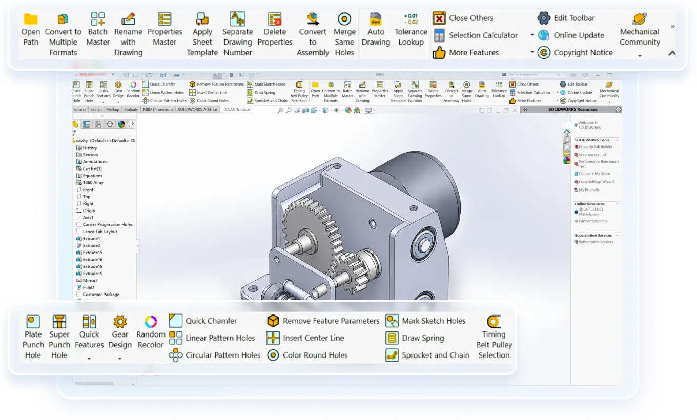
Common Exploded View Mistakes
- Making the exploded view in a drawing-only mindset. It is built in the assembly.
- Forgetting explode lines. Without them the reader cannot tell which hole a screw belongs to.
- Working in the main configuration. Make a separate configuration for the exploded view.
- Choosing the BOM type after placing balloons. Decide it first, and insert a new table if it has to change.
- Putting the exploded view and the orthographic views on one crowded sheet. Give the exploded view its own sheet.
FAQ
How do I make an exploded view in SolidWorks? Open the assembly, click Exploded View, choose a regular or radial step, select components, drag along the triad, click Add Step and repeat. Click Done when all parts are placed.
How do I show an exploded view in a SolidWorks drawing? Insert a model view of the assembly, right-click it and choose Show in Exploded State, or open its properties and select Show in exploded or model break state under Configuration information.
How do I add explode lines in SolidWorks? Use Explode Line Sketch in the assembly and draw route lines between components. In the drawing, make sure sketches are shown in the view.
Why are my exploded lines not showing in the drawing? Usually the explode line sketch is missing or hidden, or the view uses a configuration without the exploded view.
How do I edit an exploded view? Edit the exploded view feature in the ConfigurationManager to change steps, and edit the explode line sketch to change the lines.
Can I explode a multibody part? Yes. Create the exploded view in the part itself, or convert the bodies into an assembly with Save Bodies and explode that.
Popular Articles
Keep Learning
Engineering Drawing Examples: Annotated Part, Assembly, Exploded, Weldment and Sheet Metal Drawings
Quick answer: A good engineering drawing example shows more than the views. It shows how the views, dimensions, symbols, notes and title block work together for one specific part. The six examples below cover a machined part, a part with an inclined face, an assembly, an exploded assembly, a welded frame and a sheet metal part, and each one says why it is drawn the way it is. Use them as a pattern for your own drawings, or as exercises. Searching for engineering drawing examples mostly returns picture......
How to Export a SolidWorks Drawing to PDF, DXF and DWG (and Export Many at Once)
Quick answer: To export a SolidWorks drawing to PDF, use File > Save As, choose PDF as the type and set the options for colour, fonts and quality. For DXF or DWG, use File > Export As in newer versions (File > Save As in older ones), choose the type and set the export options, including whether a multi-sheet drawing goes to paper space. Most export problems come from the drawing's display quality, scale and fonts, not from the file type. The drawing is finished and checked, and now someone needs it in......
SolidWorks Weldment Drawing: Views, Cut List, Balloons, and Weld Symbols
Quick answer: A SolidWorks weldment drawing shows a welded frame in a few views of the whole weldment, a cut list that lists each structural member with its length and quantity, balloons tied to that list, and weld symbols that say how each joint is made. Build the views and the Weldment Cut List table from the weldment part, add balloons so their numbers follow the cut list, and bring in or add weld symbols last. The drawing is only as good as the cut list in the part, so check the properties and the......
Drawing Views in SolidWorks: Orthographic, Isometric, Section, Auxiliary, Detail, and Break Views
Quick answer: Drawing views are 2D pictures of a 3D model. Orthographic views (front, top, right) show true shapes and carry the dimensions, an isometric view shows the part's general form, and derived views handle special jobs: section views for the inside, auxiliary views for inclined faces, detail views for small features, and break and crop views for long or crowded views. In SolidWorks, you place a base view first and derive the others from it, which keeps them aligned and linked to their parent.......
SolidWorks Exploded View: Create It, Add Explode Lines, and Show It on a Drawing
Quick answer: An exploded view is built in the assembly, not in the drawing. Click Exploded View, add steps that move components along an axis, add explode lines with Explode Line Sketch, then on the drawing select a model view of the assembly and turn on Show in exploded or model break state. Balloons on that view read from the BOM as usual, and most missing explode lines come down to sketch display or the wrong configuration. The shop gets twelve part drawings and a pile of parts. Nothing says which......
Assembly Drawing vs Detail Drawing in SolidWorks: What Goes on Each, and How to Build the Assembly Drawing
Quick answer: An assembly drawing shows how the parts of a product fit together, with views, a bill of materials and balloons that link each part to its row. A detail drawing shows one part with everything needed to make it. In SolidWorks, you build the assembly drawing from the assembly, add a section view where it helps, insert the BOM and balloons, and add an exploded view when the reader needs the order of assembly (see our exploded view guide). The shop gets twelve part drawings and a pile of par......