How to Show and Hide Lines in a SolidWorks Drawing: Hidden Lines, Tangent Edges, Centerlines, and Bend Lines
14 min
- Where a Line Comes From
- Hidden Lines
- Tangent Edges and Fillet Lines
- Centerlines and Center Marks
- Bend Lines on Sheet Metal Flat Patterns
- Sketches and Other Stray Lines
- Line Style, Thickness and Layers
- Example: Where Each Line on the Plate Drawing Comes From
- Fixing the Usual Line Problems
- Where JLCCAN Fits
- Common Mistakes With Drawing Lines
- FAQ
Quick answer: A line is missing from a SolidWorks drawing for one of three reasons, and each has its own control. Model edges (hidden lines, tangent edges) follow the view's display style and the Show Hidden Edges and Hide/Show Edges tools. Annotation lines (centerlines, center marks) are inserted on view creation or with the Centerline and Center Mark tools. Sketch and bend lines are shown from the View menu. How a line looks (style, thickness) is separate and is set in Document Properties > Line Font.
You insert a view and the hole is a plain circle with no centerline. Or the fillets show a faint line across every rounded edge that you did not ask for. Or the flat pattern of a sheet metal part has no bend lines at all. Each looks like the same problem, which is a line that is wrong, and the fix depends on where that line comes from.
This guide sorts the lines into their sources, then covers hidden lines, tangent edges, centerlines and center marks, bend lines and stray sketch lines, and how to control line style and thickness. It ends with a symptom table. For the surrounding workflow, see our guide to creating a SolidWorks 3D to 2D drawing.
Key Takeaways
- A line is missing or extra for one of three reasons, model edges, annotations, or sketch and bend lines, and each has its own control, so the first step is finding which kind it is.
- Hidden Lines Visible on a whole assembly view makes it unreadable, and Show Hidden Edges on selected components is the more precise tool.
- Centerlines and center marks are annotations, so changing the display style cannot bring them back; turn on automatic insertion in Document Properties > Detailing or add them with the Centerline tool.
- Since SolidWorks 2022 bend lines have their own toggle (View > Bend Lines), and hiding them also hides the bend notes.
Where a Line Comes From
Before changing a setting, find out which kind of line it is.
| Line | Source | Where to control it |
|---|---|---|
| Visible edges | The model's geometry | The view's display style |
| Hidden edges | The model's geometry behind a face | Display style, Show Hidden Edges, Hide/Show Edges |
| Tangent edges | The transitions of fillets and rounds | The Tangent Edge setting, per view or by default |
| Centerlines and center marks | Annotations added to the view | Document Properties > Detailing, or the Centerline and Center Mark tools |
| Sketch lines | Sketches in the model | View > Hide/Show > Sketches |
| Bend lines | The Flat Pattern feature of a sheet metal part | View > Bend Lines |
| How any line looks | Line style and thickness | Line Format toolbar, Document Properties > Line Font The first column answers most of the questions people ask. Hidden lines are not centerlines and the settings do not overlap, so changing the display style will never bring back a missing centerline. |
Hidden Lines
A hidden line is an edge behind a face, drawn dashed so the reader can see features that are inside the part. Each drawing view has a display style, set from the View toolbar or the view's PropertyManager:
- Wireframe shows all edges.
- Hidden Lines Visible shows visible edges and hidden edges, with hidden edges drawn in the style set in Line Font.
- Hidden Lines Removed shows only edges that can be seen from the chosen direction.
- Shaded With Edges and Shaded show the part shaded.
- You can set the default for new views under Tools > Options > System Options > Drawings > Display Style. A view created from an existing view, such as a projected view, takes the display style of its source view and not the default, which is why a new view sometimes does not match the template.
Showing hidden lines for one feature only
Hidden Lines Visible on a whole assembly view is rarely what you want. Every part behind every other part shows, and the view becomes unreadable. Show Hidden Edges is the more precise tool. In a view set to Hidden Lines Removed, right-click a feature or component (in the view or the FeatureManager tree) and choose Show/Hide > Show Hidden Edges. Or right-click the view, open Properties and use the Show Hidden Edges tab to list the items. SolidWorks Help notes it works in high-quality views and not in draft-quality views, so if the option is unavailable, check the view's display quality.
The Hide/Show Edges tool on the Line Format toolbar does the opposite. Select edges individually or by box, and hide or restore them. It is the right tool for a stray line that no display setting reaches.
A drafting practice worth following: show a hidden line only when it adds information the visible views do not. A blind tapped hole in a side view usually earns its dashed lines. Every hidden edge in a complex assembly rarely does.
Tangent Edges and Fillet Lines
Tangent edges are the transition lines between rounded or filleted faces. They appear in Hidden Lines Visible and Hidden Lines Removed views, and the most common ones are fillet edges. Pictorial views (isometric and similar) often show them, and orthographic views (front, top, right) usually remove them.
The tangent edge display has four options.
| Option | Result |
|---|---|
| Visible | A solid line |
| Use font | A line in the style defined in Document Properties > Line Font |
| Removed | Not displayed |
| Hide ends | Hides the start and end segments of tangent edges To change one view, right-click it (in the graphics area or the FeatureManager tree), choose Tangent Edge and pick a mode. To change the default for all new views, go to Options > Display Style and choose under Tangent edges in new views. The Hide/Show Edges tool also has options for them. One more route comes from the model: suppress the fillets in a configuration, so they never appear in the drawing. If fillet lines keep appearing on a view you thought you had set, check which view it was created from, because derived views inherit. |
Centerlines and Center Marks
Centerlines and center marks are annotations, not model edges. They mark the axes of holes and cylinders and the centers of circles, and they are what a machinist uses to find hole positions.
- Automatic. In Document Properties > Detailing, under Auto insert on view creation, select Centerlines (and the center mark options for holes, fillets and slots, in parts and assemblies). Every new view then gets them. They are not inserted automatically in Large Assembly Mode or when the assembly exceeds the large-assembly threshold.
- Manual centerline. On the Annotation tab, click Centerline and select a cylindrical face (every feature it covers), two edges (a line between them), or the view itself to insert centerlines in every suitable feature.
- Manual center mark. Click Center Mark and select a circle or arc. The tool has options for patterns (linear and circular) and for slots, and it has a Layer setting in drawings with named layers.
- Symmetry lines. These are centerlines. Select two parallel edges of the symmetric part, such as the top and bottom, and the centerline runs through the middle.
- SolidWorks avoids duplicating centerlines. Dimensioning to a centerline also shortens the extension lines automatically, which is one reason to add them before you dimension (see our SolidWorks dimensioning).
- Size, extension and font of center marks are set in Document Properties > Centerlines/Center Marks. If marks are too short or too long for the scale of your drawing, change them there and not mark by mark.
Bend Lines on Sheet Metal Flat Patterns
Bend lines are the most common "missing line" complaint for sheet metal. They do not come from the view's display style. They are stored in the Flat Pattern feature of the part.
When you insert a flat pattern view, SolidWorks creates a derived configuration in the part and places the flattened view with bend notes. If the bend lines are missing:
- Check the View menu. SolidWorks Help and reseller documentation (CATI, GoEngineer) say that since SOLIDWORKS 2022 bend lines are separate from sketches, so they have their own toggle (View, or the heads-up View menu, then Bend Lines). Earlier versions tie them to sketches (View > Hide/Show > Sketches). Hiding the bend lines also hides the bend notes.
- Check the bend line sketch. In the flat pattern, the bend line sketch may be set to hide. Right-click it and choose Show.
- Check the bend notes separately. Hiding bend lines can also remove the bend notes. To bring them back, right-click the view, open Properties and tick the bend notes option. If notes were never there, the drawing's document property for displaying bend notes may be off.
- Do not expect notes on every view. Users report that projected views of a flat pattern show the lines but not the notes, because the option is available only on the original flat pattern view. If you need them on another view, add a note or place the flat pattern again in the orientation you want.
- If bend lines disappear after you reopen the drawing, the usual cause is the derived configuration: the flat pattern was regenerated, so show the bend lines again from the part's Flat Pattern feature.
Sketches and Other Stray Lines
Sketch geometry in the model can appear in a drawing when you do not want it. Turn sketches off from the View menu (View > Hide/Show > Sketches), and turn them on when you want them, for example to show a construction line. The same applies to other reference geometry: if a view shows more than the part, check the View > Hide/Show display toggles first, and the Hide/Show Edges tool second.
Line Style, Thickness and Layers
What a line looks like is separate from whether it shows.
- Defaults for the whole drawing: Document Properties > Line Font sets the style and thickness for each line type (visible edges, hidden edges, tangent edges, and so on). Set it once in the drawing template, not drawing by drawing (see our drawing template guide).
- One line or one group: select it and use the Line Format toolbar to change style or thickness.
- Layers: a named layer can have its own colour, style and thickness. Annotations such as center marks can be assigned to a layer when you insert them. Layers help when you need to turn a whole class of lines on and off, such as construction lines before release.
- If you find yourself changing line weights by hand on every drawing, the Line Font settings in the template are wrong. Line weight is also a matter of standard: a visible line is thick, a hidden line thinner and dashed, and a centerline thin with long and short dashes (see our guide to drawing symbols and standards).
Example: Where Each Line on the Plate Drawing Comes From
Take the plate from our dimensioning and hole guides, with four clearance holes, two tapped holes and a rounded corner.
| What you see | Source | Setting that controls it |
|---|---|---|
| Outline of the plate | Visible edges | Display style (Hidden Lines Removed) |
| Dashed lines for the blind tapped holes in the side view | Hidden edges of two features | Show Hidden Edges on those features only |
| Faint line where the corner round meets the flat | Tangent edge | Tangent Edge: Removed in orthographic views |
| Crosshair and axis lines through the holes | Centerlines and center marks | Auto insert on view creation |
| Thread circle around the tapped holes | Cosmetic thread | The hole's cosmetic thread option (see our Hole Wizard guide) |
| Line weights and dash pattern | Line Font | Document Properties, in the template Six lines, six different controls. A reader sees one drawing, and the author has to remember which control does what. |
Fixing the Usual Line Problems
| Symptom | Likely cause | Fix |
|---|---|---|
| No dashed lines in a view | Hidden Lines Removed is on | Switch the view to Hidden Lines Visible, or use Show Hidden Edges on a feature |
| Hidden lines show for every part in an assembly | Hidden Lines Visible on a whole view | Use Hidden Lines Removed and add Show Hidden Edges for selected components |
| Show Hidden Edges is unavailable | The view is in draft quality | Set the view to high quality |
| Faint lines across fillets | Tangent edges visible | Right-click the view, Tangent Edge, Removed |
| New view does not match the template | It was derived from a view with different settings | Set the source view, or the default in Display Style |
| Holes have no centerlines | Auto insert is off, or the assembly is a large assembly | Turn on Centerlines in Document Properties > Detailing, or add them manually |
| Bend lines missing | Bend lines or their sketch are hidden, or the flat pattern was regenerated | View > Bend Lines, show the bend line sketch |
| Bend notes missing | Notes option off in the view or the document properties | Tick it in the view's properties |
| Extra lines on the view | Sketches or other reference geometry displayed | View menu toggles, then Hide/Show Edges |
| Lines too thin when printed | Line Font thickness | Change the thickness in Document Properties > Line Font |
Where JLCCAN Fits
Line display is mostly a setting, so most of the work happens once, in the template. A plugin helps with what happens after: views created in bulk. JLCCAN's Auto-Drawing creates the main views and applies dimensions and annotations in batch, and the features page lists a Rotate View tool under drawing tools, which rotates a drawing view. The existing guide on our blog describes the scope of Auto-Drawing in detail.
The product team confirmed that views created by Auto-Drawing use the plugin's own display settings and not the template's. A template set up for hidden lines, tangent edges and centerlines therefore does not carry over to the generated views, so the first generated drawing needs a check against your drawing standard.
For your own drawings the advice stays the same: set Document Properties once and put the result in the template. For generated drawings, check the first one for hidden lines, tangent edges and centerlines before releasing a batch.
JLCCAN Auto-Drawing generates standard views and dimension chains straight from your SolidWorks parts, so you can spend your time on engineering review, not repetitive setup
Free Download >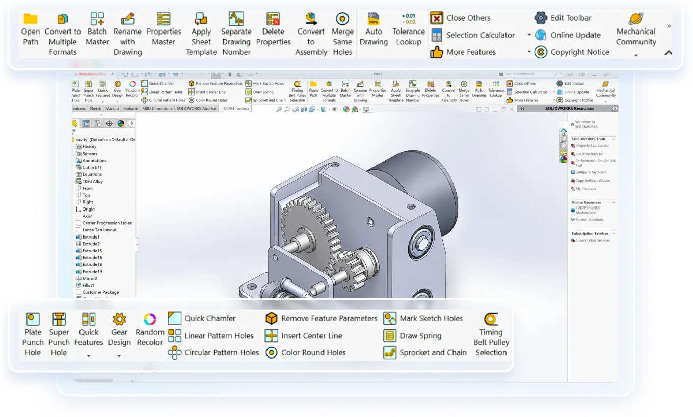
Common Mistakes With Drawing Lines
- Changing the display style to fix a missing centerline. Centerlines are annotations. The display style cannot bring them back.
- Using Hidden Lines Visible on a whole assembly view. Use Show Hidden Edges on the components that matter.
- Fixing line weights drawing by drawing. Set Line Font in the template.
- Forgetting that derived views inherit. A projected view takes the settings of its source view.
- Hiding bend lines and losing the bend notes with them. They are linked.
- Leaving sketches displayed after release. Stray construction lines look like part of the design.
- Showing every hidden line. Show those that add information.
FAQ
How do I show hidden lines in a SolidWorks drawing? Select the view and choose Hidden Lines Visible in the display style, or right-click a feature or component and choose Show/Hide > Show Hidden Edges to show hidden lines for that item only.
How do I hide tangent edges or fillet lines? Right-click the view, choose Tangent Edge and select Removed. To change the default for new views, use Options > Display Style under Tangent edges in new views.
How do I add centerlines to a SolidWorks drawing? Use the Centerline tool on the Annotation tab and select a face, two edges or the whole view. To add them to every new view, turn on Centerlines under Auto insert on view creation in Document Properties > Detailing.
Why are my bend lines not showing in a flat pattern drawing? Bend lines are stored in the Flat Pattern feature. Check the View menu for Bend Lines, make sure the bend line sketch is shown, and check the bend notes option in the view's properties.
How do I make lines thicker in a SolidWorks drawing? For all lines of a type, change the thickness in Document Properties > Line Font. For selected lines, use the Line Format toolbar.
How do I hide sketches in a drawing? Turn off Sketches in the View menu. Use the Hide/Show Edges tool for individual edges that remain.
Popular Articles
Keep Learning
Engineering Drawing Examples: Annotated Part, Assembly, Exploded, Weldment and Sheet Metal Drawings
Quick answer: A good engineering drawing example shows more than the views. It shows how the views, dimensions, symbols, notes and title block work together for one specific part. The six examples below cover a machined part, a part with an inclined face, an assembly, an exploded assembly, a welded frame and a sheet metal part, and each one says why it is drawn the way it is. Use them as a pattern for your own drawings, or as exercises. Searching for engineering drawing examples mostly returns picture......
How to Export a SolidWorks Drawing to PDF, DXF and DWG (and Export Many at Once)
Quick answer: To export a SolidWorks drawing to PDF, use File > Save As, choose PDF as the type and set the options for colour, fonts and quality. For DXF or DWG, use File > Export As in newer versions (File > Save As in older ones), choose the type and set the export options, including whether a multi-sheet drawing goes to paper space. Most export problems come from the drawing's display quality, scale and fonts, not from the file type. The drawing is finished and checked, and now someone needs it in......
SolidWorks Weldment Drawing: Views, Cut List, Balloons, and Weld Symbols
Quick answer: A SolidWorks weldment drawing shows a welded frame in a few views of the whole weldment, a cut list that lists each structural member with its length and quantity, balloons tied to that list, and weld symbols that say how each joint is made. Build the views and the Weldment Cut List table from the weldment part, add balloons so their numbers follow the cut list, and bring in or add weld symbols last. The drawing is only as good as the cut list in the part, so check the properties and the......
Drawing Views in SolidWorks: Orthographic, Isometric, Section, Auxiliary, Detail, and Break Views
Quick answer: Drawing views are 2D pictures of a 3D model. Orthographic views (front, top, right) show true shapes and carry the dimensions, an isometric view shows the part's general form, and derived views handle special jobs: section views for the inside, auxiliary views for inclined faces, detail views for small features, and break and crop views for long or crowded views. In SolidWorks, you place a base view first and derive the others from it, which keeps them aligned and linked to their parent.......
SolidWorks Exploded View: Create It, Add Explode Lines, and Show It on a Drawing
Quick answer: An exploded view is built in the assembly, not in the drawing. Click Exploded View, add steps that move components along an axis, add explode lines with Explode Line Sketch, then on the drawing select a model view of the assembly and turn on Show in exploded or model break state. Balloons on that view read from the BOM as usual, and most missing explode lines come down to sketch display or the wrong configuration. The shop gets twelve part drawings and a pile of parts. Nothing says which......
Assembly Drawing vs Detail Drawing in SolidWorks: What Goes on Each, and How to Build the Assembly Drawing
Quick answer: An assembly drawing shows how the parts of a product fit together, with views, a bill of materials and balloons that link each part to its row. A detail drawing shows one part with everything needed to make it. In SolidWorks, you build the assembly drawing from the assembly, add a section view where it helps, insert the BOM and balloons, and add an exploded view when the reader needs the order of assembly (see our exploded view guide). The shop gets twelve part drawings and a pile of par......