Engineering Drawing Symbols and Standards: A Practical Guide for SolidWorks Users
13 min
- Which Standard Applies: ASME or ISO
- Line Types and What They Mean
- Dimension and Feature Symbols
- Surface, Weld, Datum and GD&T Symbols
- Scale and Projection
- Reading a Callout Set: The Plate Example
- Setting the Drafting Standard in SolidWorks
- Where JLCCAN Fits
- Common Symbol and Standard Mistakes
- FAQ
Quick answer: Engineering drawing symbols are the shorthand that tells a reader the diameter, depth, thread, finish or tolerance of a feature without a paragraph of text. Which symbols to use depends on the drafting standard: ASME Y14 in the U.S., ISO in most other places. In SolidWorks the standard is set once under Document Properties > Drafting Standard, and the symbols are added with Smart Dimension, Hole Callout, the Surface Finish and Geometric Tolerance tools, or the Add Symbol button in notes.
Two engineers can draw the same bracket and produce drawings that look unrelated. One uses third-angle views and decimal inches, the other first-angle views and millimetres. Both are correct, and a reader who does not know which standard applies will misread one of them.
This guide is a reference for the symbols on mechanical drawings, grouped by what they do, with the standard behind each one and the SolidWorks tool that adds it. It also covers scale and projection, and finishes by reading a real callout set from the plate used in our other guides. For the surrounding workflow, see our guide to creating a SolidWorks 3D to 2D drawing.
Key Takeaways
- Which symbols apply depends on the drafting standard, ASME Y14 or ISO, and it is set once under Document Properties > Drafting Standard and carried in the template.
- ASME drawings normally use third-angle projection and ISO drawings first-angle, so a view on the unexpected side can be a standards difference and not an error.
- Symbols without a keyboard key should be inserted with the Add Symbol option, because a look-alike character may not survive export.
- Scale never changes dimension values, so a reader should take sizes from the dimensions and not from measuring the drawing.
Which Standard Applies: ASME or ISO
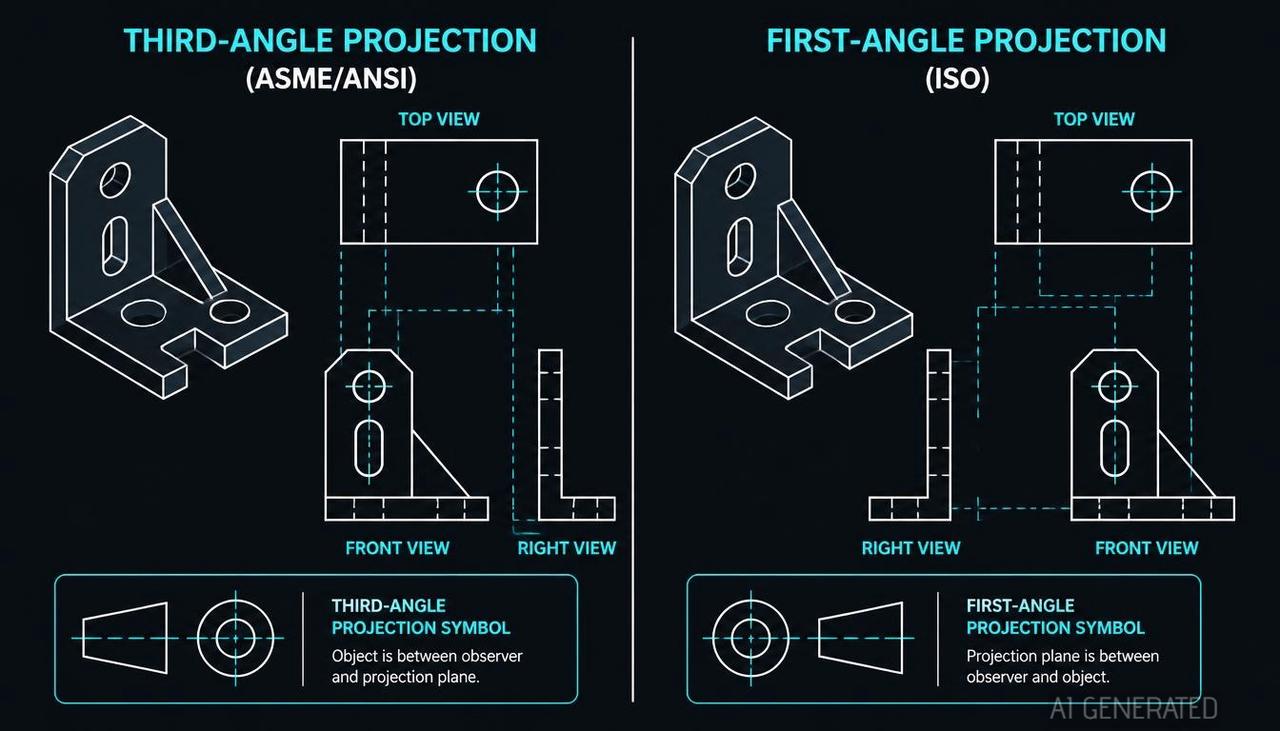
A drafting standard is a rulebook for how a drawing looks and what its marks mean. Two families cover most mechanical work.
- ASME Y14 is the American series. ASME Y14.5 covers dimensioning and tolerancing, and the rest of the Y14 family covers views, drawing types, parts lists, revisions and surface texture symbols.
- ISO is the international series, used across Europe and most of Asia. ISO 128 sets the general principles for technical drawings, with separate standards for dimensioning, tolerancing, sheets, scales and title blocks.
- National standards (DIN, JIS, BSI, GB, GOST) exist too, and most of them are close to ISO. Here are the standards you will meet most often, with the area each covers.
| Area | ASME | ISO |
|---|---|---|
| General drawing practice, lines and views | ASME Y14.3, Y14.24, Y14.100 | ISO 128 series, ISO 5456 (projection methods) |
| Dimensioning and tolerancing | ASME Y14.5 | ISO 129-1 (dimensioning), ISO 1101 (geometrical tolerancing), ISO 2768 (general tolerances) |
| Sheet sizes and layout | ASME Y14.1 | ISO 5457 |
| Title block data | ASME Y14.100 | ISO 7200 |
| Scales | Per Y14 practice | ISO 5455 |
| Surface texture symbols | ASME Y14.36 (with ASME B46.1) | ISO 1302, now ISO 21920-1 |
| Threads in drawings | ASME Y14.6 | ISO 6410 |
| Parts lists | ASME Y14.34 | Per ISO 7573 The table is a map and not a substitute for the standards. Editions change, so check the current one before you quote a clause. For title block fields and sheet sizes, see our title block guide. The differences that catch people out most often: |
- Projection. ASME drawings normally use third-angle projection and ISO drawings normally use first-angle, so a view placed on the "wrong" side is a standards difference, not an error. The drawing carries a projection symbol so the reader knows.
- Units and notation. Inch drawings and millimetre drawings use different conventions for decimals and tolerances.
- Callouts. Thread and hole notes are written differently (M6×1 against 1/4-20 UNC, for example), and SolidWorks changes some callout behaviour with the standard, as noted in our Hole Wizard guide.
Line Types and What They Mean
Before any symbol, the lines carry meaning. A drawing is read first by its line weight and pattern.
| Line | Appearance | Meaning |
|---|---|---|
| Visible (object) line | Thick, continuous | Outline of what you can see |
| Hidden line | Medium or thin, dashed | Edges behind a surface |
| Center line | Thin, long and short dashes | Axis of a hole, shaft or symmetric part |
| Dimension and extension lines | Thin, continuous | Carry the dimension, never part of the object |
| Cutting plane line | Thick, with arrowheads at the ends | Where a section view is taken |
| Section (hatch) lines | Thin, continuous, usually at 45° | Cut material in a section view |
| Break line | Thin, freehand or zigzag | Part is shortened to save space |
| Phantom line | Thin, long dash and two short dashes | Alternate positions or adjacent parts In SolidWorks, the Line Format toolbar changes the style and thickness of a selected line, and Document Properties > Line Font sets the defaults for each line type. If your hidden lines look the same as visible lines, the fault is almost always in those defaults and not in the views. |
Dimension and Feature Symbols
These are the marks you use on almost every part. Where a glyph does not exist on a keyboard, drawings use an abbreviation.
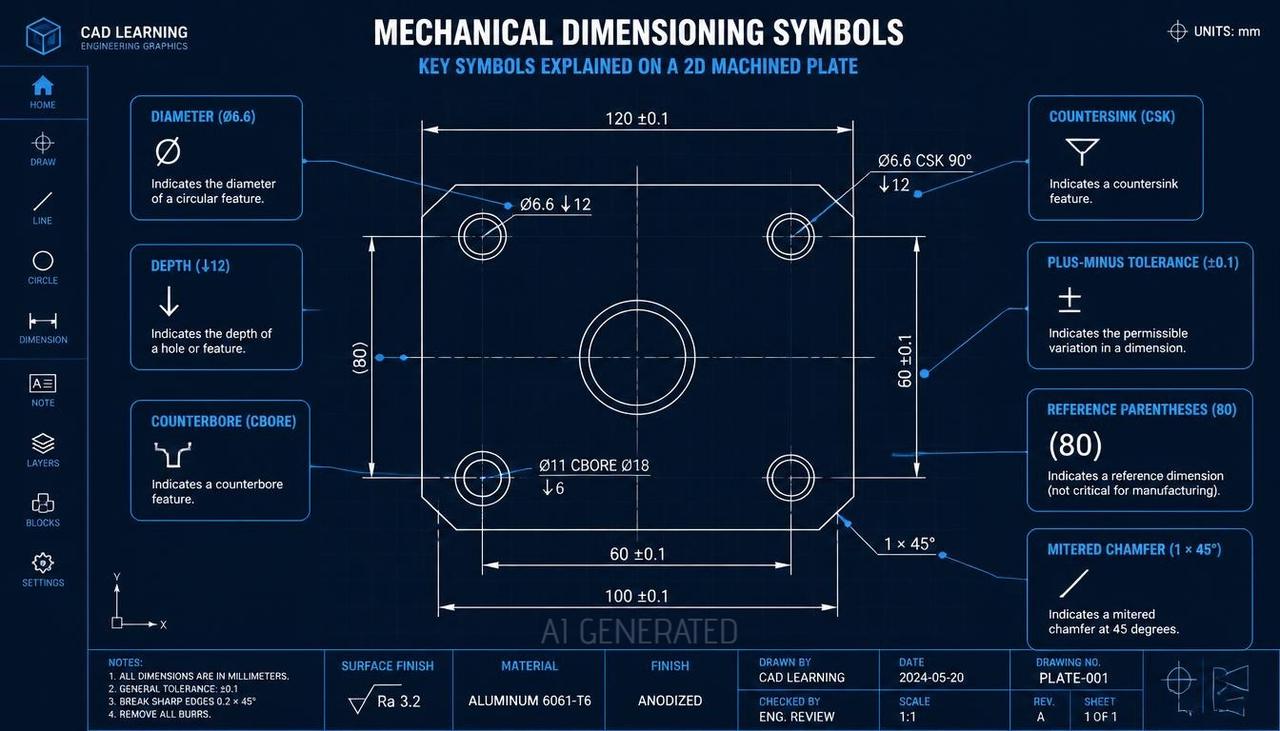
| Symbol or abbreviation | Meaning | Example | In SolidWorks |
|---|---|---|---|
| Ø | Diameter | Ø6.6 | Added automatically by Smart Dimension on circles |
| R | Radius | R5 | Smart Dimension on arcs |
| SR / SØ | Spherical radius or diameter | SR12 | Dimension text symbols |
| ± | Plus or minus tolerance | 20 ±0.1 | Tolerance settings in the dimension |
| ° | Degrees | 45° | Angular dimension |
| × (after a number) | Number of instances | 6× Ø6.6 | Hole callout counts instances |
| THRU | Hole goes all the way through | Ø6.6 THRU | Hole Wizard end condition |
| TYP | Typical, repeats elsewhere | R3 TYP | Text in the dimension |
| ( ) | Reference dimension | (80) | Driven dimension in parentheses |
| Boxed number | Basic dimension, toleranced by geometry | [20] | Basic dimension option |
| CBORE, CSK | Counterbore, countersink | CBORE Ø11 × 6.5 | Hole Wizard hole callout |
| M6×1 | Metric thread, size × pitch | M6×1 ↓ 12 | Cosmetic thread callout |
| Depth symbol | Depth of a hole or pocket | ↓ 12 | Hole callout and dimension text |
| □ | Square feature | □10 | Dimension text symbols |
| Chamfer note | Distance × angle | 1 × 45° | Chamfer Dimension The rules behind how to place these (once per feature, outside the view, from a datum) are covered in our SolidWorks dimensioning. Reference dimensions and chamfer dimensions each have their own guide: reference dimension guide and chamfer dimension guide. To add a symbol that has no keyboard key, double-click the note or dimension text and use the Add Symbol option in the Note PropertyManager (or the symbol list in the dimension text box). Symbols inserted this way stay as symbols when the drawing is exported, which typing a look-alike character does not guarantee. |
Surface, Weld, Datum and GD&T Symbols
These four families are specialist topics. Each gets one line here.
| Family | What it states | In SolidWorks | Deeper reference |
|---|---|---|---|
| Surface texture | Roughness (Ra) and finish requirements | Surface Finish tool, Annotation tab | Surface roughness symbols, JLCCNC |
| Weld | Type, size and location of a weld | Weld Symbol tool, Annotation tab (or Insert > Annotations > Weld Symbol) | Our weldment drawing guide |
| Datum feature and target | The reference a part is located and measured from | Datum Feature tool | GD&T in CNC machining, JLCCNC |
| Geometric tolerance | Form, orientation, location and runout limits | Geometric Tolerance tool | GD&T flatness, true position One SolidWorks point worth knowing. The drafting standard changes how these symbols are drawn, so a surface finish symbol under ISO and one under ANSI are not interchangeable even when the value is the same. |
Scale and Projection
Scale is the ratio between the size of the drawn view and the real part. It does not change the dimension values, which always state the real size, and a reader should never measure a drawing to find a dimension.
ISO 5455 recommends a short list of ratios.
| Type | Common ratios |
|---|---|
| Full size | 1:1 |
| Reduction | 1:2, 1:5, 1:10, 1:20, 1:50, 1:100 |
| Enlargement | 2:1, 5:1, 10:1, 20:1, 50:1 Other ratios are used, but sticking to the list keeps drawings consistent across a team. A view that is not drawn to scale is marked as such, typically with the note NTS (not to scale). In SolidWorks there are two places to set scale, and mixing them up causes most of the "my view is the wrong size" questions. |
- Sheet scale is set in the sheet properties (right-click the sheet, choose Properties). New views take this scale by default.
- View scale is set in the view's own PropertyManager. Choose between using the sheet scale, the parent scale (for detail and projected views) or a custom scale.
- A detail view is the one place a custom scale is the norm. It magnifies a small region, and its label shows its own scale.
- The type of projection (first angle or third angle) is also a sheet property, and it is saved in the drawing template and not in the sheet format, as covered in our drawing template guide.
Reading a Callout Set: The Plate Example
Here are the marks you would find on the 120 × 80 × 10 mm plate used in our dimensioning and hole guides, with what each one tells the shop.
| On the drawing | Meaning | Standard area | SolidWorks tool |
|---|---|---|---|
| 120, 80, 10 | Overall size in millimetres | Dimensioning | Smart Dimension or Model Items |
| 4× Ø6.6 THRU | Four clearance holes, through | Hole callout | Hole Wizard, Hole Callout |
| 2× M6×1 ↓ 12 | Two tapped holes, thread depth 12 | Thread callout | Cosmetic thread |
| (80) | Reference dimension, not toleranced | Dimensioning | Driven dimension |
| 1 × 45° | Edge break | Chamfer | Chamfer Dimension |
| Surface symbol with Ra 3.2 | Machined surface, roughness limit | Surface texture | Surface Finish |
| Datum feature A | The left edge the plate locates on | Datum | Datum Feature |
| A–A with thick arrowed line | Section taken at that plane | Views and lines | Section View |
| Projection symbol | First or third angle | Sheet property | Sheet properties Every row maps to a standard and a tool. When something on a drawing looks unfamiliar, finding which row it belongs to usually answers it. |
Setting the Drafting Standard in SolidWorks
Open Options, choose the Document Properties tab and select Drafting Standard. The overall drafting standard can be ANSI, ISO, DIN, JIS, BSI, GOST or GB, or a custom standard you create. Each time you pick one, the base standard of every detail (dimensions, notes, balloons, tables and so on) updates to match.
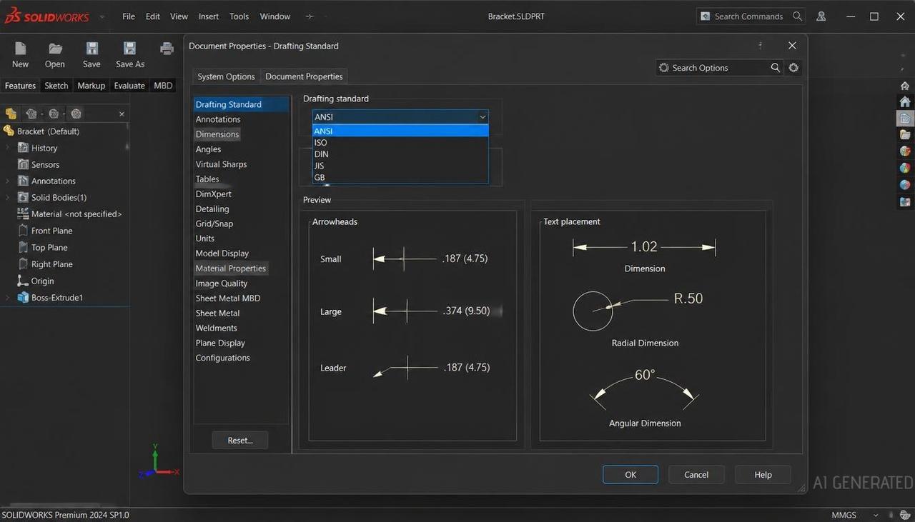
Three practical points from SolidWorks Help.
- A custom standard is a saved set of annotation settings. You can copy, rename, export it to a file and load it on another machine, which is the simplest way to give a team one company standard.
- Not every setting travels with the standard. SolidWorks Help says the standard copies annotation settings, and the remaining document properties are saved with the drawing template. A custom standard on its own will not make two machines agree. The template has to carry the rest.
- Changing the standard on an existing drawing changes how its annotations draw. Review dimensions, balloons and callouts afterwards, because arrowheads, text placement and symbols can shift.
- The working rule: choose the standard first, put it in the template, and keep one template per standard. A drawing that starts under ANSI and is switched to ISO halfway often ends up with mixed conventions.
Where JLCCAN Fits
Standard drawings repeat the same symbols on every part, which is where a plugin helps. JLCCAN's features page lists Auto Drawing & Dimensioning, which generates drawings from 3D models and applies linear dimensions, dimension chains, hole tables, GD&T and surface finish annotations in batch, and a Rotate View tool in the drawing tools. Batch Manager is listed for title block replacement, which matters when a standard or company format changes.
The product team confirmed how the automatic annotations behave. They follow the GB standard, the Chinese national standard, so for ANSI or ISO drawings the generated annotations need a review against the standard the customer asked for. They are inserted as native SolidWorks annotations, and the symbols covered are surface roughness, parallelism, perpendicularity, flatness, coaxiality, symmetry, circular runout and total runout. JLCCAN does not have a weld symbol function, so weld symbols are added with SolidWorks' own Weld Symbol tool.
The reviewing step does not change with automation. Whoever releases the drawing should still check that the symbols match the standard the customer asked for.
JLCCAN Auto-Drawing generates standard views and dimension chains straight from your SolidWorks parts, so you can spend your time on engineering review, not repetitive setup
Free Download >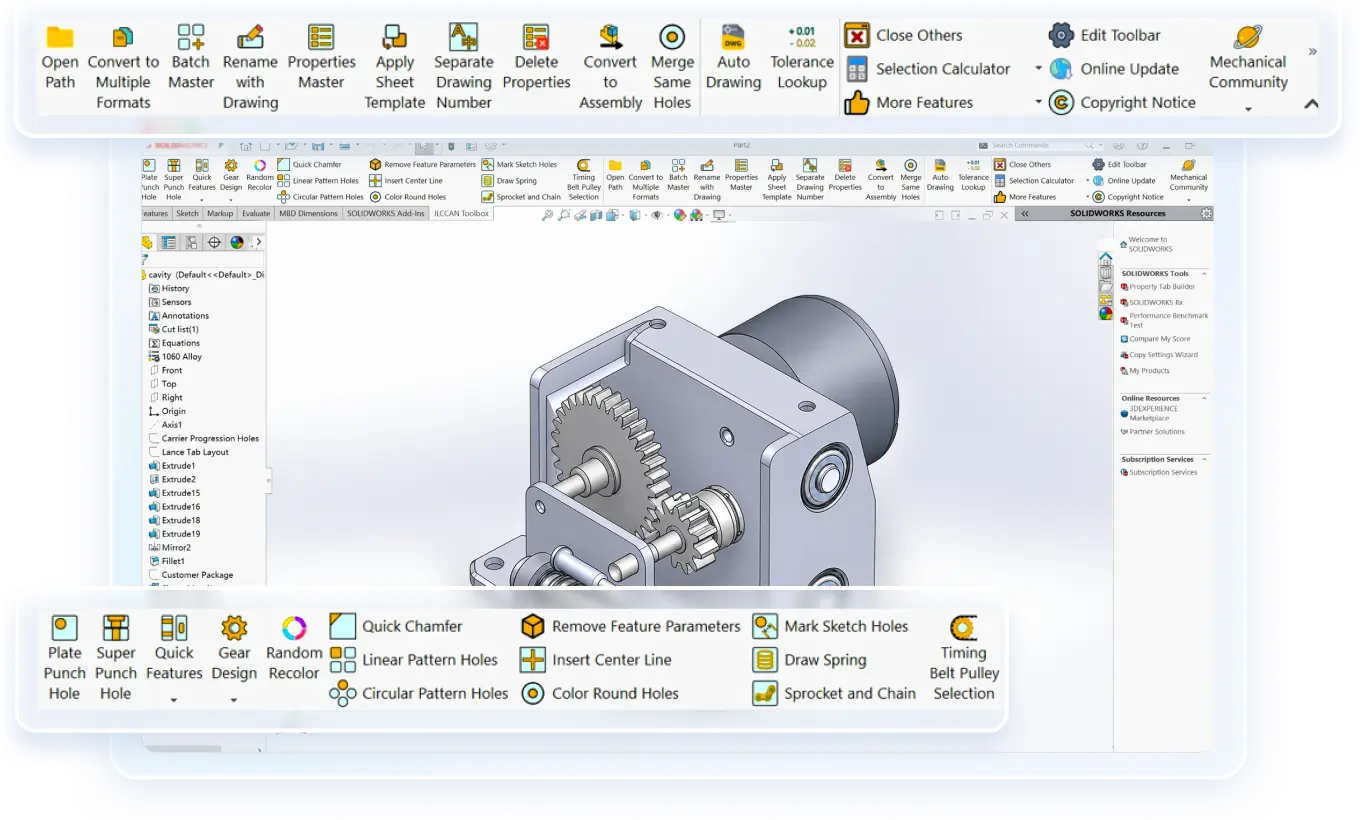
Common Symbol and Standard Mistakes
- Mixing first-angle and third-angle views on one drawing. The projection symbol says one thing and the layout says another.
- Typing look-alike characters. A letter O for a diameter sign or a lowercase x for the multiplication sign may not survive export. Use the symbol tool.
- Using an ISO surface finish symbol on an ASME drawing, or the reverse. The shapes and rules differ.
- Setting the standard after the drawing is finished. Switch it first, or review every annotation afterwards.
- Measuring the drawing. Scale is for reading shapes. Dimension values state the size.
- Overriding line weights by hand. Hand-edited weights drift. Fix the defaults in Document Properties > Line Font.
- Copying symbols from a chart for the wrong discipline. Electrical, piping and architectural charts use different symbols. Use a mechanical chart.
FAQ
What are the most common symbols on a mechanical drawing? Diameter (Ø), radius (R), plus or minus (±), the number of instances (for example 4×), THRU, thread callouts such as M6×1, chamfer notes, surface finish symbols and datum symbols.
What is the difference between ASME and ISO drawing standards? ASME Y14 is the American series, with Y14.5 covering dimensioning and tolerancing, and it normally uses third-angle projection. ISO is the international series, with ISO 128 and related standards, and it normally uses first-angle projection. Callouts, symbols and notation also differ in detail.
How do I choose the drafting standard in SolidWorks? With a drawing open, go to Options > Document Properties > Drafting Standard and pick ANSI, ISO, DIN, JIS, BSI, GOST, GB or a custom standard.
How do I change the scale of a view in SolidWorks? Change the sheet scale in the sheet properties to rescale views that follow it, or select a view and set a custom scale in its PropertyManager.
How do I insert a diameter or other symbol in a SolidWorks drawing? Dimensions on circles get the diameter symbol automatically. For notes and text, double-click to edit and use the Add Symbol option, so the symbol stays a real symbol.
Which standard should my drawings follow? The one your customer or company specifies. If none is specified, pick one, set it in the template and apply it to every drawing.
Popular Articles
Keep Learning
Engineering Drawing Examples: Annotated Part, Assembly, Exploded, Weldment and Sheet Metal Drawings
Quick answer: A good engineering drawing example shows more than the views. It shows how the views, dimensions, symbols, notes and title block work together for one specific part. The six examples below cover a machined part, a part with an inclined face, an assembly, an exploded assembly, a welded frame and a sheet metal part, and each one says why it is drawn the way it is. Use them as a pattern for your own drawings, or as exercises. Searching for engineering drawing examples mostly returns picture......
How to Export a SolidWorks Drawing to PDF, DXF and DWG (and Export Many at Once)
Quick answer: To export a SolidWorks drawing to PDF, use File > Save As, choose PDF as the type and set the options for colour, fonts and quality. For DXF or DWG, use File > Export As in newer versions (File > Save As in older ones), choose the type and set the export options, including whether a multi-sheet drawing goes to paper space. Most export problems come from the drawing's display quality, scale and fonts, not from the file type. The drawing is finished and checked, and now someone needs it in......
SolidWorks Weldment Drawing: Views, Cut List, Balloons, and Weld Symbols
Quick answer: A SolidWorks weldment drawing shows a welded frame in a few views of the whole weldment, a cut list that lists each structural member with its length and quantity, balloons tied to that list, and weld symbols that say how each joint is made. Build the views and the Weldment Cut List table from the weldment part, add balloons so their numbers follow the cut list, and bring in or add weld symbols last. The drawing is only as good as the cut list in the part, so check the properties and the......
Drawing Views in SolidWorks: Orthographic, Isometric, Section, Auxiliary, Detail, and Break Views
Quick answer: Drawing views are 2D pictures of a 3D model. Orthographic views (front, top, right) show true shapes and carry the dimensions, an isometric view shows the part's general form, and derived views handle special jobs: section views for the inside, auxiliary views for inclined faces, detail views for small features, and break and crop views for long or crowded views. In SolidWorks, you place a base view first and derive the others from it, which keeps them aligned and linked to their parent.......
SolidWorks Exploded View: Create It, Add Explode Lines, and Show It on a Drawing
Quick answer: An exploded view is built in the assembly, not in the drawing. Click Exploded View, add steps that move components along an axis, add explode lines with Explode Line Sketch, then on the drawing select a model view of the assembly and turn on Show in exploded or model break state. Balloons on that view read from the BOM as usual, and most missing explode lines come down to sketch display or the wrong configuration. The shop gets twelve part drawings and a pile of parts. Nothing says which......
Assembly Drawing vs Detail Drawing in SolidWorks: What Goes on Each, and How to Build the Assembly Drawing
Quick answer: An assembly drawing shows how the parts of a product fit together, with views, a bill of materials and balloons that link each part to its row. A detail drawing shows one part with everything needed to make it. In SolidWorks, you build the assembly drawing from the assembly, add a section view where it helps, insert the BOM and balloons, and add an exploded view when the reader needs the order of assembly (see our exploded view guide). The shop gets twelve part drawings and a pile of par......