SolidWorks Reference Dimensions: Driven vs Driving, and How to Show Them on a Drawing
10 min
- What Is a Reference Dimension?
- Driven vs Driving Dimensions in SolidWorks
- How to Add Reference Dimensions
- Show Reference Dimensions in Parentheses
- Switching Between Driven and Driving
- Reference Dimensions and Model Items
- Example: One Reference Dimension on the Plate
- Common Mistakes With Reference Dimensions
- Where JLCCAN Fits
- FAQ
Quick answer: A reference dimension is a value shown for information only. It repeats or is derived from other dimensions, carries no tolerance, and is written in parentheses so nobody manufactures to it. In SolidWorks it is a driven dimension: it reads its value from the geometry and cannot change the model, and dimensions you add to a drawing view with Smart Dimension are of this kind. The parentheses are on by default, except for ordinate dimensions.
The number in parentheses sits next to a row of toleranced dimensions: (80). The inspector skips it, the machinist ignores it, and the engineer who added it uses it as a quick check. When it goes wrong, it is because someone treats it as a requirement, or because someone turns a driven dimension into a driving one and the model moves.
This guide explains what a reference dimension is, how it differs from other kinds of dimension, how SolidWorks separates driven from driving dimensions, and how to add, show and hide reference dimensions. It uses the plate with six holes from our SolidWorks dimensioning. For the rules that decide when a reference dimension is worth adding, that guide is the better starting point.
Key Takeaways
- A reference dimension shows a size for information only, carries no tolerance and does not drive the model, and SolidWorks shows it in parentheses by default.
- Dimensions added in a drawing are reference dimensions, so changing a value means changing it in the part.
- In a sketch, right-clicking a dimension and choosing Driven switches it, and SolidWorks offers the Make Dimension Driven? dialog when a new dimension would over-define the sketch.
- The parentheses default is set under Document Properties > Dimensions, and putting it in the drawing template makes every drawing follow the same rule.
What Is a Reference Dimension?
A reference dimension gives a size that the drawing already defines some other way. It is either a repeat of a dimension stated elsewhere or a value derived from others, such as the overall length of a part whose features are dimensioned one by one. It is for information, so it does not govern manufacture or inspection and it normally has no tolerance. Drawings mark it by enclosing the value in parentheses.
The two main standards agree on the idea and differ on the word. ASME Y14.5 calls it a reference dimension, and ISO 129-1 calls the same thing an auxiliary dimension. Both use parentheses.
The usual reasons to add one are to show an overall size that would otherwise need adding up, to give a reviewer a number to check against after a revision, and to record a stock size. The usual reason not to add one is that it hands the reader a second number for something already dimensioned, which our dimensioning rules warn against for toleranced dimensions. The parentheses are what make the repeat acceptable, and they are also why a drawing full of them stops saying which values matter.
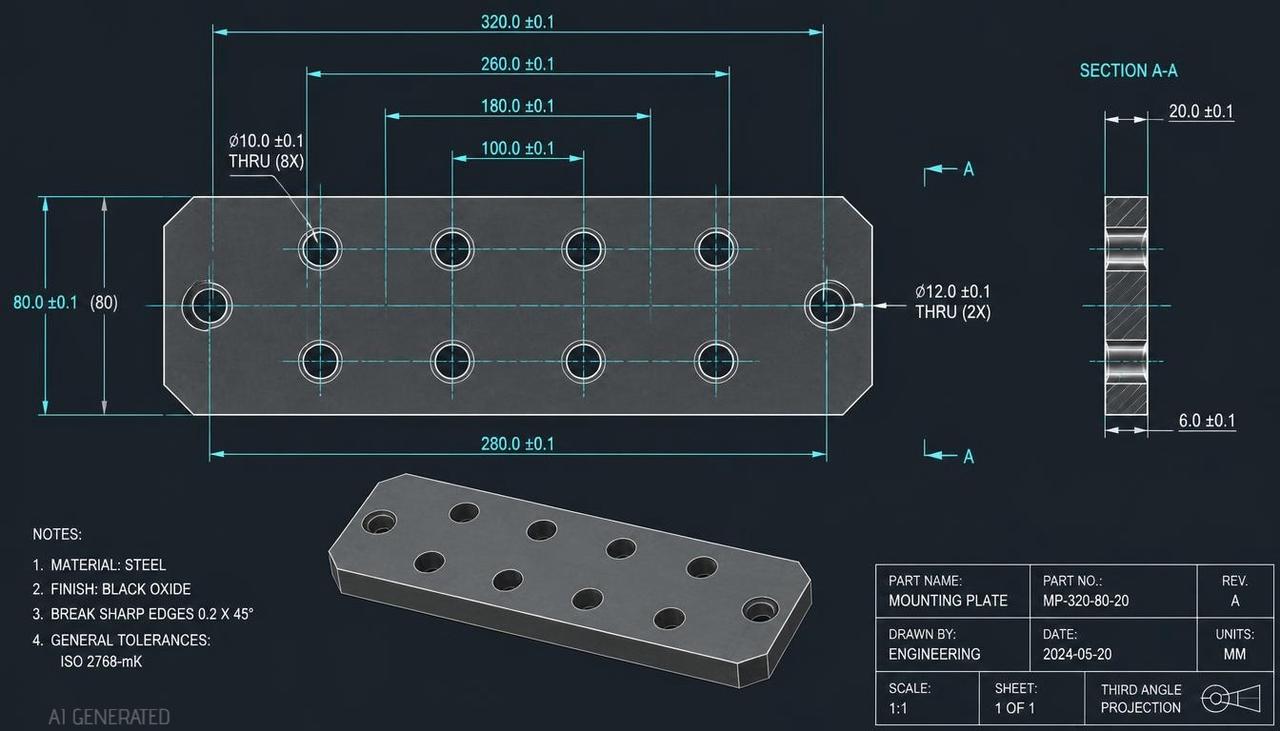
Reference, basic and toleranced dimensions
Three kinds of number sit on a drawing, and they are easy to confuse.
| Kind | How it is marked | Tolerance | What it means |
|---|---|---|---|
| Toleranced dimension | Plain value, tolerance beside it or in the general block | Yes | The part is made and inspected to it |
| Basic dimension | Value in a box | No, the tolerance comes from a geometric control | A theoretically exact location or size |
| Reference dimension | Value in parentheses | No | Information only, never inspected A reference dimension must never be the only dimension for a feature. If a feature has a reference dimension and no other, the drawing does not define it. |
Driven vs Driving Dimensions in SolidWorks
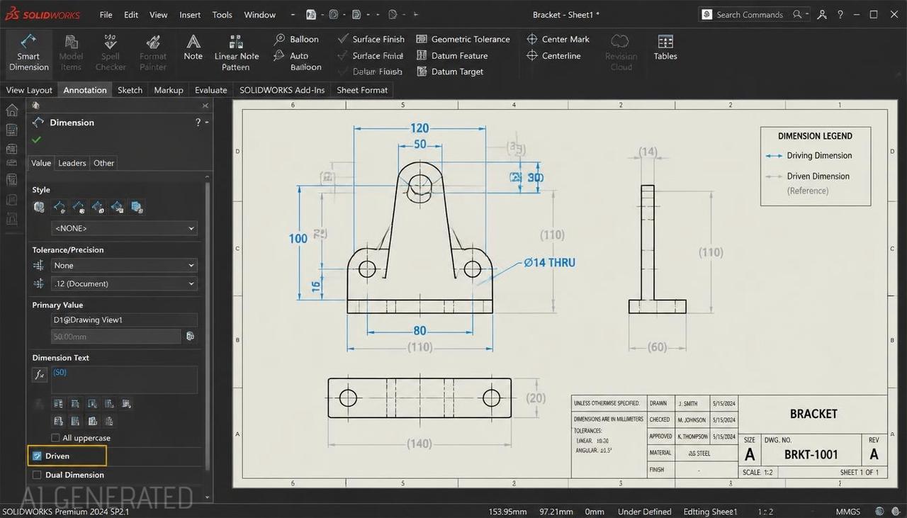
SolidWorks uses two words for the same split. A driving dimension controls the geometry: change its value and the model changes. A driven dimension reports the geometry: its value is measured from the model, you cannot type a new one, and changing the model changes the dimension. SolidWorks Help describes a reference dimension as one that shows measurements of the model but does not drive it.
| Driving dimension | Driven (reference) dimension | |
|---|---|---|
| Value comes from | What you type | The geometry |
| Edit the value | Yes, the model changes | No |
| Typical source | Sketch and feature dimensions, Model Items | Smart Dimension on a drawing view |
| Default appearance on a drawing | Plain value | In parentheses |
| If the feature is suppressed | Goes with the feature | Hidden automatically, per SolidWorks Help |
| Role | Defines the part | Checks the part Two more points from SolidWorks Help are worth knowing. In a drawing, ordinate and baseline dimensions are types of reference dimension, which is why Autodimension and the ordinate tool produce numbers you cannot edit. And ordinate dimensions are the exception to the parentheses default, because their value reads from a common zero and parentheses would clutter the row. |
How to Add Reference Dimensions
On a drawing
On the Annotation tab, click Smart Dimension and select the geometry. Dimensions added to a drawing view this way are reference dimensions, so there is nothing extra to turn on. The same applies to the Ordinate Dimension and Baseline Dimension tools. If you want the drawing to show the model's own driving dimensions, use Model Items instead, which imports them from the part (see below).
In a sketch
In a sketch, the same Smart Dimension tool adds a driving dimension by default. When a new dimension would over-define the sketch, SolidWorks warns and offers to make the new dimension driven instead. You can also switch a dimension on purpose: right-click it and choose Driven, and choose it again to make it driving. This is useful when you want a measurement in the sketch, such as the length of a line you constrained other ways, without constraining the geometry any further.
Show Reference Dimensions in Parentheses
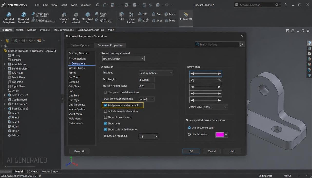
SolidWorks Help says reference dimensions are shown in parentheses by default, except ordinate dimensions. That default is a document setting. If the parentheses are missing on your drawings, or if every Smart Dimension in your template gets them when you would rather add them by hand, change it in Document Properties under Dimensions. The option is called Add parentheses by default, in Tools > Options > Document Properties > Dimensions. For a single dimension, select it and use Add Parentheses under Dimension Text in the Dimension PropertyManager. Driven dimensions are also grey by default, and the colour is set under System Options > Colors (Dimensions, Non Imported (Driven)).
Set this in the drawing template, not drawing by drawing, as described in our drawing template guide. A mix of bracketed and unbracketed reference dimensions on one set of drawings is how a reader ends up unsure which numbers to trust.
Switching Between Driven and Driving
The risk is on the model side. Turning a driven dimension into a driving one in a sketch adds a constraint, and if the typed value differs from the measured one, the geometry moves. On a part that has already been released, that is a design change, not a drawing tweak. SolidWorks may stop you if the new constraint conflicts with the existing ones. In a sketch, SolidWorks offers the Make Dimension Driven? dialog when a new dimension would over-define it, and right-clicking a dimension and choosing Driven switches it between driven and driving. SolidWorks Help only says that dimensions added in a drawing are reference dimensions, so to change a value, change it in the part.
The practical rule is to leave drawing dimensions driven. Change the driving dimension in the part, let the drawing follow, and look at the reference dimensions afterwards, since that is what they are for. If a reference dimension changes value after a revision, something upstream moved, and you find out on the drawing.
Reference Dimensions and Model Items
Model Items pulls the driving dimensions from the part into the drawing, so the drawing starts from the dimensions the designer chose. Reference dimensions are what you add on top with Smart Dimension. The combination works well, with one check: a Model Items dimension and a reference dimension can show the same feature twice. That is acceptable only if the second is in parentheses and there is a reason for it. Otherwise delete it, because each feature should be dimensioned once (see our SolidWorks dimensioning).
Example: One Reference Dimension on the Plate
Take the 120 × 80 × 10 mm plate with six holes at 20, 60 and 100 mm from the left edge. The hole positions are driving dimensions imported with Model Items, measured from the left edge, with a tolerance of ±0.1 mm each. The drawing also carries one reference dimension: the 80 mm spacing between hole 1 and hole 3, in parentheses.
That number is derived: 100 minus 20. It carries no tolerance and nobody manufactures to it. Its job shows up after a revision. If someone moves hole 3 to 110 mm in the model, the driving dimension changes to 110 and the reference dimension changes to (90), and a reviewer who sees the 90 knows the pattern has changed since the last release. The reference dimension did not control the plate, it told the reader that the plate had changed.
Common Mistakes With Reference Dimensions
- Using one as the only dimension for a feature. The feature is then undefined on the drawing.
- Adding so many that the parentheses lose their meaning. Keep them to a minimum, as ASME Y14.5 advises.
- Giving a reference dimension a tolerance. It contradicts what the parentheses say.
- Making a driven dimension driving to "fix" a number. The model moves. Change the driving dimension instead.
- Treating parentheses on a basic dimension. Basic dimensions go in a box, not in parentheses.
- Mixing bracketed and unbracketed reference dimensions. Set the default once in the template.
- Duplicating a Model Items dimension without parentheses. The reader sees two numbers for one feature.
Where JLCCAN Fits
JLCCAN's features page lists Auto Linear Dimensions and Auto Dimension Chain among its drawing tools, and its Auto Drawing and Dimensioning tool applies dimensions to parts in batch. JLCCAN's product team says the dimensions it places are tied to the model, while the quantity in a hole callout does not follow it. A grey dimension colour after auto-drawing is a drawing-template setting, so it does not by itself mean the dimensions are reference dimensions.
In SolidWorks terms that points to driving dimensions and not reference ones, so a change to a value on the drawing changes the part. To see it for yourself, select a dimension in your own template and check whether its value can be edited.
JLCCAN Auto-Drawing generates standard views and dimension chains straight from your SolidWorks parts, so you can spend your time on engineering review, not repetitive setup
Free Download >
FAQ
What is a reference dimension? A value on a drawing that gives information only. It repeats or is derived from other dimensions, has no tolerance, and is written in parentheses so it is not used for manufacture or inspection.
What is the difference between a reference dimension and a driving dimension in SolidWorks? A driving dimension controls the geometry, so changing its value changes the model. A reference (driven) dimension reports a value measured from the geometry and cannot be edited.
How do I add a reference dimension in a SolidWorks drawing? Use Smart Dimension on the Annotation tab and select the geometry. Dimensions added to a drawing view this way are reference dimensions, shown in parentheses by default.
How do I show or hide the parentheses on a reference dimension? The default is the Add parentheses by default option under Tools > Options > Document Properties > Dimensions, and a single dimension can use Add Parentheses under Dimension Text in the Dimension PropertyManager. Set the default in the drawing template so every drawing follows the same rule.
Popular Articles
Keep Learning
Engineering Drawing Examples: Annotated Part, Assembly, Exploded, Weldment and Sheet Metal Drawings
Quick answer: A good engineering drawing example shows more than the views. It shows how the views, dimensions, symbols, notes and title block work together for one specific part. The six examples below cover a machined part, a part with an inclined face, an assembly, an exploded assembly, a welded frame and a sheet metal part, and each one says why it is drawn the way it is. Use them as a pattern for your own drawings, or as exercises. Searching for engineering drawing examples mostly returns picture......
How to Export a SolidWorks Drawing to PDF, DXF and DWG (and Export Many at Once)
Quick answer: To export a SolidWorks drawing to PDF, use File > Save As, choose PDF as the type and set the options for colour, fonts and quality. For DXF or DWG, use File > Export As in newer versions (File > Save As in older ones), choose the type and set the export options, including whether a multi-sheet drawing goes to paper space. Most export problems come from the drawing's display quality, scale and fonts, not from the file type. The drawing is finished and checked, and now someone needs it in......
SolidWorks Weldment Drawing: Views, Cut List, Balloons, and Weld Symbols
Quick answer: A SolidWorks weldment drawing shows a welded frame in a few views of the whole weldment, a cut list that lists each structural member with its length and quantity, balloons tied to that list, and weld symbols that say how each joint is made. Build the views and the Weldment Cut List table from the weldment part, add balloons so their numbers follow the cut list, and bring in or add weld symbols last. The drawing is only as good as the cut list in the part, so check the properties and the......
Drawing Views in SolidWorks: Orthographic, Isometric, Section, Auxiliary, Detail, and Break Views
Quick answer: Drawing views are 2D pictures of a 3D model. Orthographic views (front, top, right) show true shapes and carry the dimensions, an isometric view shows the part's general form, and derived views handle special jobs: section views for the inside, auxiliary views for inclined faces, detail views for small features, and break and crop views for long or crowded views. In SolidWorks, you place a base view first and derive the others from it, which keeps them aligned and linked to their parent.......
SolidWorks Exploded View: Create It, Add Explode Lines, and Show It on a Drawing
Quick answer: An exploded view is built in the assembly, not in the drawing. Click Exploded View, add steps that move components along an axis, add explode lines with Explode Line Sketch, then on the drawing select a model view of the assembly and turn on Show in exploded or model break state. Balloons on that view read from the BOM as usual, and most missing explode lines come down to sketch display or the wrong configuration. The shop gets twelve part drawings and a pile of parts. Nothing says which......
Assembly Drawing vs Detail Drawing in SolidWorks: What Goes on Each, and How to Build the Assembly Drawing
Quick answer: An assembly drawing shows how the parts of a product fit together, with views, a bill of materials and balloons that link each part to its row. A detail drawing shows one part with everything needed to make it. In SolidWorks, you build the assembly drawing from the assembly, add a section view where it helps, insert the BOM and balloons, and add an exploded view when the reader needs the order of assembly (see our exploded view guide). The shop gets twelve part drawings and a pile of par......