Drawing Views in SolidWorks: Orthographic, Isometric, Section, Auxiliary, Detail, and Break Views
14 min
- Which View for Which Job
- Orthographic Projection
- Isometric Views
- Section Views
- Auxiliary and Detail Views
- Break and Crop Views
- Align, Rotate and Move Views
- Example: Views for a Bracket
- Fixing the Usual View Problems
- Where JLCCAN Fits
- Common Drawing View Mistakes
- FAQ
Quick answer: Drawing views are 2D pictures of a 3D model. Orthographic views (front, top, right) show true shapes and carry the dimensions, an isometric view shows the part's general form, and derived views handle special jobs: section views for the inside, auxiliary views for inclined faces, detail views for small features, and break and crop views for long or crowded views. In SolidWorks, you place a base view first and derive the others from it, which keeps them aligned and linked to their parent.
A drawing with the right views is easy to read. A drawing with the wrong ones sends the machinist to the phone: the slot on the inclined face looks short because it is seen at an angle, the thread inside the bore is not visible, and the corner radius is too small to read at the sheet scale. Each of those has a standard view that solves it.
This guide covers the main view types, what each is for, how to create them in SolidWorks, and how they relate to each other. It also explains orthographic and isometric projection, because they are the base of every set of views. For the surrounding workflow, see our guide to creating a SolidWorks 3D to 2D drawing.
Key Takeaways
- The view should follow the job: orthographic views for shape, isometric for understanding, section for internal features, auxiliary for inclined faces and detail views for small features.
- Projected, auxiliary and section views stay aligned with their parent and move only along the projection direction until Break Alignment is used.
- The Section View PropertyManager offers vertical, horizontal, auxiliary and aligned cutting lines, and Section Scope controls which components are cut.
- Auto-Drawing does not add section, detail or auxiliary views on parts, so those stay manual steps.
Which View for Which Job
SolidWorks groups views into standard views (the first ones you place) and derived views (made from another view). SolidWorks Help lists the derived types as projected, auxiliary, detail, crop, broken-out section, break, section, aligned section, alternate position and relative views.
| View | Use it to show | SolidWorks tool | Related to |
|---|---|---|---|
| Base (model) view | The first view of a part or assembly | Model View, View Palette | The model |
| Projected view | Front, top, right, and other sides, in line with a parent | Projected View | A parent view, aligned with it |
| Isometric view | The overall 3D form | Model View with isometric orientation, View Palette | The model |
| Section view | The inside of a part | Section View | A parent view, with a section line |
| Aligned section view | A section that bends to reach features at an angle | Section View, aligned option | A parent view |
| Broken-out section | A local cut to show one inside feature | Broken-out Section | A parent view |
| Auxiliary view | The true shape of an inclined face | Auxiliary View | An edge in a parent view |
| Detail view | A small feature enlarged | Detail View | A circled region of a parent view |
| Break view | A long part shortened | Break | The view itself |
| Crop view | Only part of a view | Crop View | The view itself |
| Alternate position view | A mechanism in two positions, superimposed | Alternate Position View | An assembly view Three of these (section, detail and auxiliary) stay linked to their parent. |
Orthographic Projection
An orthographic projection shows the part from one direction at a time, with every line of sight perpendicular to the view plane. The result has no perspective: a surface parallel to the view keeps its true size and shape, so you can dimension it. A part has six principal views (front, back, top, bottom, left, right), and most parts need only two or three of them. Choose the fewest views that remove ambiguity.
The views are arranged by one of two conventions.
- Third-angle projection puts the top view above the front view and the right view to the right of it. It is the usual convention under ASME.
- First-angle projection puts the top view below the front view and the right view to the left. It is the usual convention under ISO.
- The projection type is a sheet property, and the drawing carries a symbol so the reader knows which one applies. See our guide to drawing standards for the standards, and our drawing template guide for where to set it.
- In SolidWorks, place the front view first, then use Projected View and move the cursor to the side you want. A projected view stays aligned with its parent, so moving the parent moves the child on the shared axis. That alignment is what makes a set of views read as one object. Standard 3 View inserts the three standard views in one step, with the front view fixed in line with the other two, which can only move horizontally or vertically. For an unusual orientation, a relative view is defined by two orthogonal faces or planes of the model.
Isometric Views
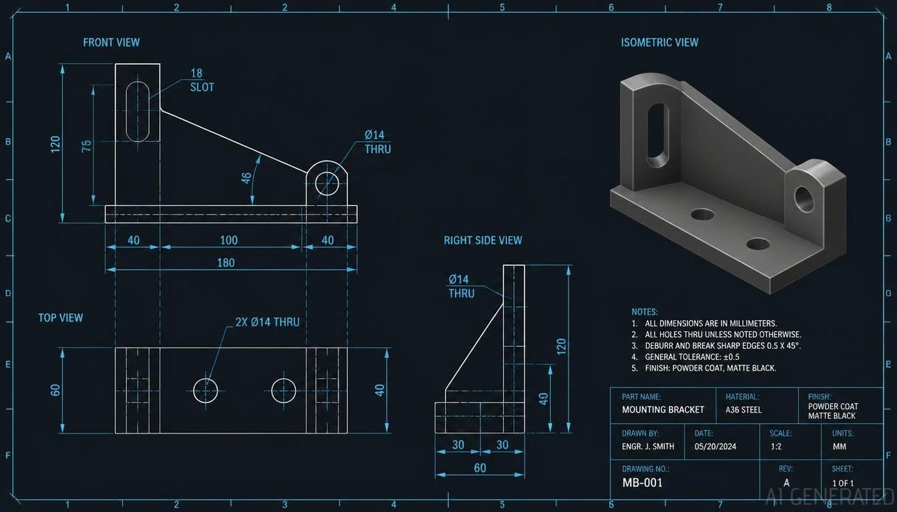
An isometric view shows the part in three dimensions on a flat sheet, with the three main axes drawn 120° apart. Vertical edges stay vertical, and the other two sets of edges run at 30° to the horizontal.
The common question is whether an isometric drawing is 2D or 3D. It is a 2D drawing that shows a 3D appearance. It is flat on the paper, and no depth is stored in the drawing.
A small point about scale. A true isometric projection shortens every axis by the same factor, about 0.816 (the square root of 2/3). An isometric drawing in textbooks often uses full length along the axes instead, which makes it larger and is simpler to draw by hand. A SolidWorks isometric view is a projection of the 3D model, so you should not measure it. Dimension the orthographic views and use the isometric to show the form.
To add one in SolidWorks, drag the Isometric view from the View Palette, or insert a Model View and choose the isometric orientation. You can also project a view from an isometric parent. In SolidWorks Help for the Model View PropertyManager, the orientation list holds the six standard views and Isometric, and Trimetric and Dimetric sit under More views. From SolidWorks 2022 the Predefined View PropertyManager also offers Trimetric and Dimetric. A custom orientation can be set in the view's PropertyManager. Isometric views are useful on the first sheet beside the orthographic views, and in an exploded form on an assembly drawing (see our assembly drawing guide).
Section Views
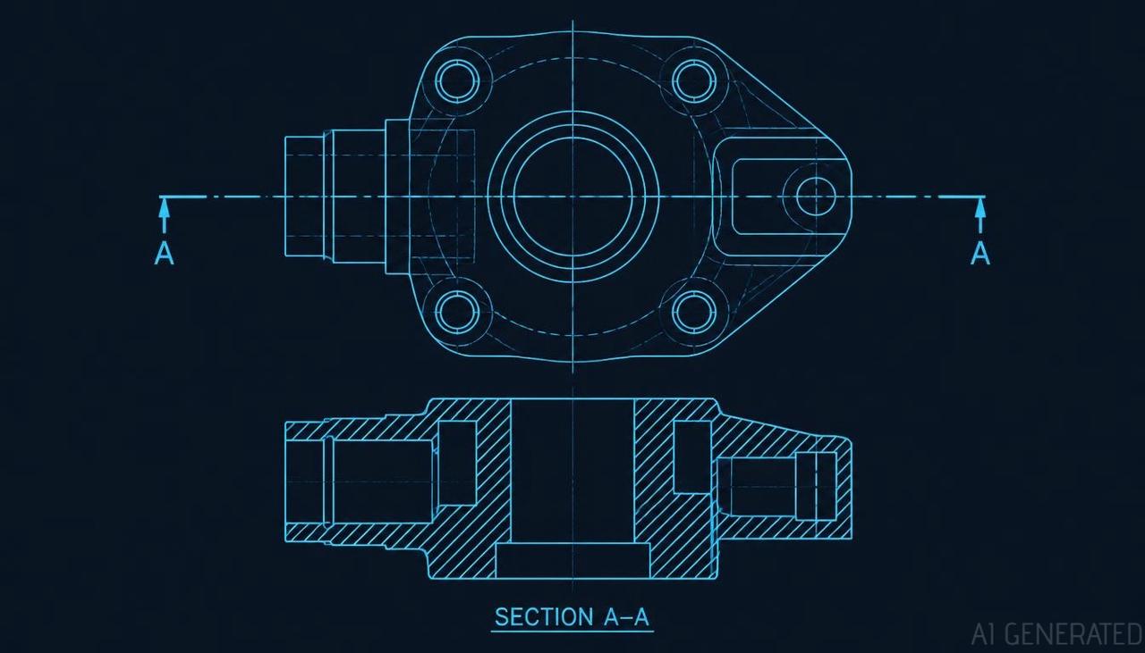
A section view shows what a cutting plane reveals, with the cut material hatched. Use one when hidden lines would be too many to read, or to show internal features such as bores, ribs and wall thickness.
- Create it. Click Section View, choose a vertical, horizontal or other cutting line, place it on the parent view and click to position the result. The section gets a label (A–A) and the parent gets a section line with arrows.
- Types. A full section cuts the whole part, a half section shows one quarter removed on a symmetric part, an offset section bends the cutting line through several features, and an aligned section rotates one part of the cut into the plane of view. In SolidWorks, the Section View PropertyManager offers vertical, horizontal, auxiliary and aligned cutting lines, an offset cut comes from adding a single, arc or notch offset to the cutting line, and Half Section has its own tab with eight directions.
- Section scope. In an assembly you choose which components are not cut, which our assembly drawing guide covers.
- Broken-out section. A local cut inside a view, for one feature, without a full section.
- The section line is an annotation on the parent. If you move or edit the parent, the section follows, and changing the section line updates the section view.
Auxiliary and Detail Views
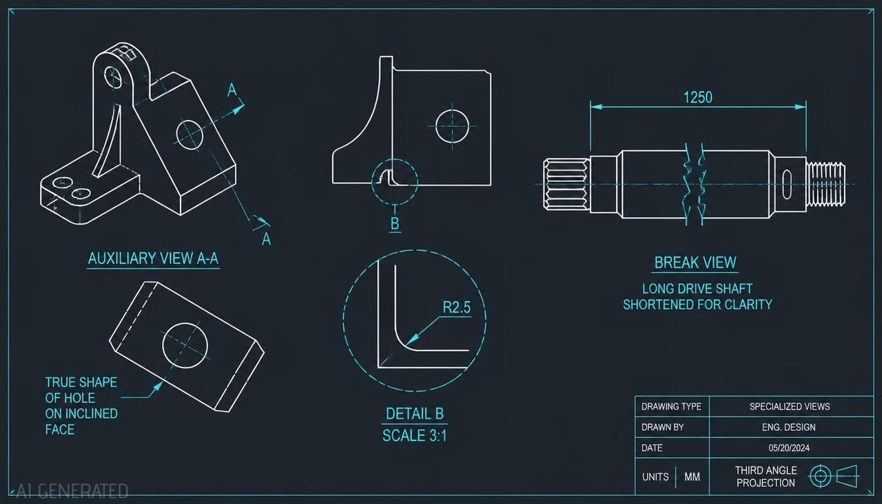
Auxiliary view. A face that is inclined to the main planes appears foreshortened in the standard views. An auxiliary view projects perpendicular to an inclined edge, so the face appears in its true shape and the features on it can be dimensioned correctly. In SolidWorks you make it with Auxiliary View, by selecting the reference edge in a parent view; our https://jlccan.com/blog/solidworks-auxiliary-view-when-and-how-to-create-it has the steps and the partial auxiliary view.
Detail view. A detail view encloses a region of a view in a circle (or another outline) and shows it enlarged, with its own label and scale. SolidWorks Help says a detail view can be made from an orthographic view, a non-planar (isometric) view, a section view, a crop view, an exploded assembly view, or another detail view. Put the circle around the feature, set the scale, and add the scale label if you need one.
Break and Crop Views
Break view. For a long part with a constant cross-section (a shaft, a rail, a tube) a break view removes the middle and draws break lines, so the part fits at a larger scale. The dimensions still show the real length. To restore the full view, right-click the break and choose Un-Break View.
Crop view. A crop view hides everything outside a closed profile you sketch. Use it to show one region of a view without a separate detail view, or to trim an assembly view down to the area that matters. To remove a crop, right-click the view and remove the crop.
Align, Rotate and Move Views
Projected and auxiliary views are aligned to their parents by default. This is helpful until you want a view somewhere else.
- Break alignment. Right-click the view and choose Alignment, then Break Alignment, to move it freely. You can restore alignment from the same menu.
- Align a view. Use the same Alignment menu to align the view horizontally or vertically to another view's origin or to a chosen edge.
- Rotate a view. Use the Rotate View tool to turn a view by an angle, for example to bring a part's long axis horizontal. A rotated view keeps its link to the model, and the views related to it update.
- Move to another sheet. Drag the view onto another sheet tab, or cut and paste it, depending on your version.
Example: Views for a Bracket
Here is a view plan for a bracket with an inclined mounting face, a bored hole and a small corner round.
| View | Type | Why |
|---|---|---|
| Front | Base view | Shows the main profile and the bore |
| Top | Projected | Shows width and hole positions |
| Right | Projected | Shows the height and the inclined face in profile |
| Auxiliary from the inclined edge | Auxiliary (partial) | True shape and slot size on the inclined face |
| A–A through the bore | Section | Wall thickness and a thread that cannot be seen from outside |
| Detail B of the corner round | Detail at 3:1 | Radius too small at the sheet scale |
| Isometric | Model view | The general form for the reader Seven views might look like a lot for a small bracket. Each answers a question the other six cannot, which is the test for adding a view. The auxiliary view has its own guide. |
Fixing the Usual View Problems
| Symptom | Likely cause | Fix |
|---|---|---|
| A projected view will not move freely | It is aligned to its parent | Break Alignment from the right-click menu |
| A view will not line up with another | Alignment was broken | Re-align by origin or by edge |
| A view is blank, or a box with a cross | The model is not loaded, or the file was moved | Load the model, or fix the reference (see our reference dimension guide) |
| The section hatch is wrong or crosses a screw | The component was cut | Use Section Scope to exclude it |
| A detail view shows the wrong region | The circle is on another view | Edit the detail circle on the parent |
| An isometric view looks too small | The sheet scale applies to all views | Give the view its own scale in its PropertyManager |
| Hidden lines show in only some views | Each view has its own display style | Set the display style per view (see our guide to lines in drawings) |
| A broken view still shows the full length | Break not applied, or restored | Apply the break, check Un-Break View was not used |
| Section view loses its link after editing | The parent view was deleted or replaced | Rebuild from a new parent |
| Rotated view dimensions look odd | Rotation changed their orientation | Re-place or re-align the dimensions |
Where JLCCAN Fits
Choosing and placing views is a repeated decision on every part. JLCCAN's Auto-Drawing generates a drawing from a part or assembly, and the existing guide on our blog describes how it works: it detects the most suitable main view, adjusts the view scale to fit the sheet, and creates the standard views. For assemblies it generates standard three views only. The features page also lists a Rotate View tool under drawing tools.
According to JLCCAN's product team, Auto-Drawing does not add section, detail or auxiliary views on parts, so those are still made by hand, and Rotate View rotates a view.
The same logic applies with or without automation. A generated set of views is a starting point, and the question to ask of each one is whether it answers something the others do not.
JLCCAN Auto-Drawing generates standard views and dimension chains straight from your SolidWorks parts, so you can spend your time on engineering review, not repetitive setup
Free Download >
Common Drawing View Mistakes
- Adding views until the sheet is full. Each view should answer a question.
- Dimensioning the isometric view. It is foreshortened, so dimension the orthographic views.
- Drawing hidden lines instead of a section. A section is clearer where the inside is complex.
- Using a detail view with a different scale and no label. The reader will not know it is enlarged.
- Breaking alignment and forgetting to re-align. Views drift apart, and the set stops reading as one object.
- Mixing first-angle and third-angle layouts. The projection symbol and the layout must agree.
- Cutting fasteners in an assembly section. Exclude them with Section Scope.
FAQ
What are the types of views in an engineering drawing? Orthographic views (front, top, side), isometric and other pictorial views, section views, auxiliary views, detail views, and break and crop views. In SolidWorks the last four are derived from a parent view.
What is orthographic projection in engineering drawing? It is a method that shows a part from one direction at a time, with every line of sight perpendicular to the view plane, so surfaces parallel to the view keep their true shape and size.
Is an isometric drawing 2D or 3D? It is a 2D drawing that shows a 3D appearance. The sheet is flat and the drawing stores no depth.
How do I add an isometric view in a SolidWorks drawing? Drag the Isometric view from the View Palette, or insert a Model View and choose the isometric orientation.
How do I add a section view in a SolidWorks drawing? Click Section View, choose a vertical, horizontal or other cutting line, place it on the parent view and click to position the result. The section gets a label (A–A) and the parent gets a section line with arrows.
How do I rotate a drawing view in SolidWorks? Use the Rotate View tool and enter an angle, or drag with the tool active. The view stays linked to the model.
How do I align or move drawing views? Use the Alignment options in the right-click menu to break, restore or set alignment, and move a view to another sheet by dragging it to the sheet tab or by cut and paste.
Popular Articles
Keep Learning
Engineering Drawing Examples: Annotated Part, Assembly, Exploded, Weldment and Sheet Metal Drawings
Quick answer: A good engineering drawing example shows more than the views. It shows how the views, dimensions, symbols, notes and title block work together for one specific part. The six examples below cover a machined part, a part with an inclined face, an assembly, an exploded assembly, a welded frame and a sheet metal part, and each one says why it is drawn the way it is. Use them as a pattern for your own drawings, or as exercises. Searching for engineering drawing examples mostly returns picture......
How to Export a SolidWorks Drawing to PDF, DXF and DWG (and Export Many at Once)
Quick answer: To export a SolidWorks drawing to PDF, use File > Save As, choose PDF as the type and set the options for colour, fonts and quality. For DXF or DWG, use File > Export As in newer versions (File > Save As in older ones), choose the type and set the export options, including whether a multi-sheet drawing goes to paper space. Most export problems come from the drawing's display quality, scale and fonts, not from the file type. The drawing is finished and checked, and now someone needs it in......
SolidWorks Weldment Drawing: Views, Cut List, Balloons, and Weld Symbols
Quick answer: A SolidWorks weldment drawing shows a welded frame in a few views of the whole weldment, a cut list that lists each structural member with its length and quantity, balloons tied to that list, and weld symbols that say how each joint is made. Build the views and the Weldment Cut List table from the weldment part, add balloons so their numbers follow the cut list, and bring in or add weld symbols last. The drawing is only as good as the cut list in the part, so check the properties and the......
Drawing Views in SolidWorks: Orthographic, Isometric, Section, Auxiliary, Detail, and Break Views
Quick answer: Drawing views are 2D pictures of a 3D model. Orthographic views (front, top, right) show true shapes and carry the dimensions, an isometric view shows the part's general form, and derived views handle special jobs: section views for the inside, auxiliary views for inclined faces, detail views for small features, and break and crop views for long or crowded views. In SolidWorks, you place a base view first and derive the others from it, which keeps them aligned and linked to their parent.......
SolidWorks Exploded View: Create It, Add Explode Lines, and Show It on a Drawing
Quick answer: An exploded view is built in the assembly, not in the drawing. Click Exploded View, add steps that move components along an axis, add explode lines with Explode Line Sketch, then on the drawing select a model view of the assembly and turn on Show in exploded or model break state. Balloons on that view read from the BOM as usual, and most missing explode lines come down to sketch display or the wrong configuration. The shop gets twelve part drawings and a pile of parts. Nothing says which......
Assembly Drawing vs Detail Drawing in SolidWorks: What Goes on Each, and How to Build the Assembly Drawing
Quick answer: An assembly drawing shows how the parts of a product fit together, with views, a bill of materials and balloons that link each part to its row. A detail drawing shows one part with everything needed to make it. In SolidWorks, you build the assembly drawing from the assembly, add a section view where it helps, insert the BOM and balloons, and add an exploded view when the reader needs the order of assembly (see our exploded view guide). The shop gets twelve part drawings and a pile of par......