SolidWorks Chamfer Dimension: How to Dimension a Chamfer and Change the Format
7 min
- Chamfer Dimension vs Smart Dimension
- How to Dimension a Chamfer
- Chamfer Text Formats
- Tolerance Options for Chamfer Dimensions
- When the Value Reads Wrong
- FAQ
Quick answer: In a SolidWorks drawing, use the Chamfer Dimension tool, not Smart Dimension, to dimension a chamfer. Select the chamfered edge first, then one of the lead-in edges, and click to place the dimension. The text format (for example 1 × 45°, 45° × 1, 1 × 1 or C1) is a document setting under Document Properties > Dimensions > Chamfer, so set it once in the template.
The edge break is the smallest feature on the part and the one most often misread. A shop sees 1.41 where the designer meant 1 × 45°, and either rounds the edge too far or asks a question that costs a day. The cause is almost always a dimension taken from the wrong thing.
This guide covers why a plain Smart Dimension does not describe a chamfer, how to use the Chamfer Dimension tool, what the text formats mean and where to change them, and what to check when the value reads wrong. For the general rules of dimensioning, see our SolidWorks dimensioning.
Key Takeaways
- The Chamfer Dimension tool reports length and angle in one callout, while Smart Dimension measures the sloped edge itself, which is 1.41 mm for a 1 mm by 45° chamfer.
- SolidWorks Help asks for the chamfered edge first and then a lead-in edge, and forum users report that the reading can change with the lead-in edge chosen.
- The text can be written as 1 × 45°, 45° × 1, 1 × 1 or C1, and the document default sets the format.
- Tolerance options differ by version, from three in the 2016 Help to a longer list in 2025, so the list in your own version is the one to use.
Chamfer Dimension vs Smart Dimension
A chamfer is described by two numbers: how far it cuts back along each face, or how far along one face and at what angle. A Smart Dimension on the angled edge measures that edge, which is the length of the sloped face and not the setback. For a 1 mm 45° chamfer, that sloped face is about 1.41 mm long (1 multiplied by the square root of 2), and 1.41 is exactly the number a reader should not mistake for the chamfer size.
The Chamfer Dimension tool reads the chamfer as a chamfer. It builds a single callout that gives the distance and the angle (or the two distances), with a leader that points at the feature. SolidWorks Help describes chamfer dimensions as having their own options for leader display, text display and X display on top of the usual dimension properties.
How to Dimension a Chamfer
- Open the view. Use a view in which the chamfer shows in profile, such as a front or side view, so the leader has something clean to point at.
- Start the tool. Click Chamfer Dimension on the Dimensions/Relations toolbar, or use Tools > Dimensions > Chamfer.
- Select the chamfered edge first. SolidWorks Help is explicit that the chamfered edge must be selected first.
- Select one of the lead-in edges. The dimension does not appear until you do this. A lead-in edge is one of the edges that runs into the chamfer.
- Click to place the dimension. The Dimension PropertyManager appears, and the tool stays active so you can dimension the next chamfer straight away. SolidWorks Help also notes that rapid dimensioning places evenly spaced dimensions.
- Click OK to close the PropertyManager when you have finished.
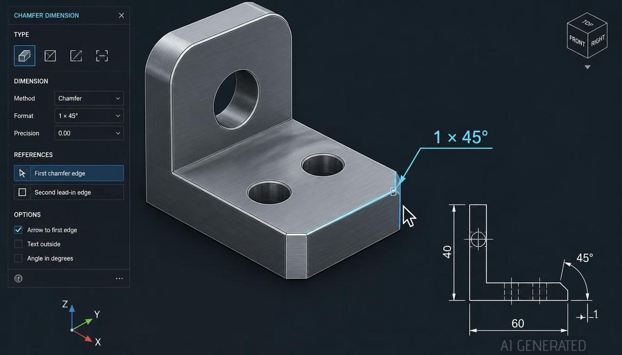
- The plate used in our other guides shows the point. Its edge break is 1 × 45°, so the callout reads 1 × 45° and the drawing needs no second number. If the same edge were dimensioned with Smart Dimension, the shop would read the 1.41 mm slope and have to work backwards.
Chamfer Text Formats
The form of the callout is a setting, not a property of the chamfer. SolidWorks Help describes the X display as the size of the X in a chamfer dimension with two numbers, and lists four formats.
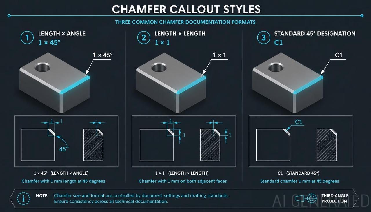
| Format | Reads as | Use it when |
|---|---|---|
| 1 × 45° | Length × Angle | The usual form for a 45° edge break or a chamfer at another angle |
| 45° × 1 | Angle × Length | Your standard or customer writes the angle first |
| 1 × 1 | Length × Length | The two setbacks differ or are given separately |
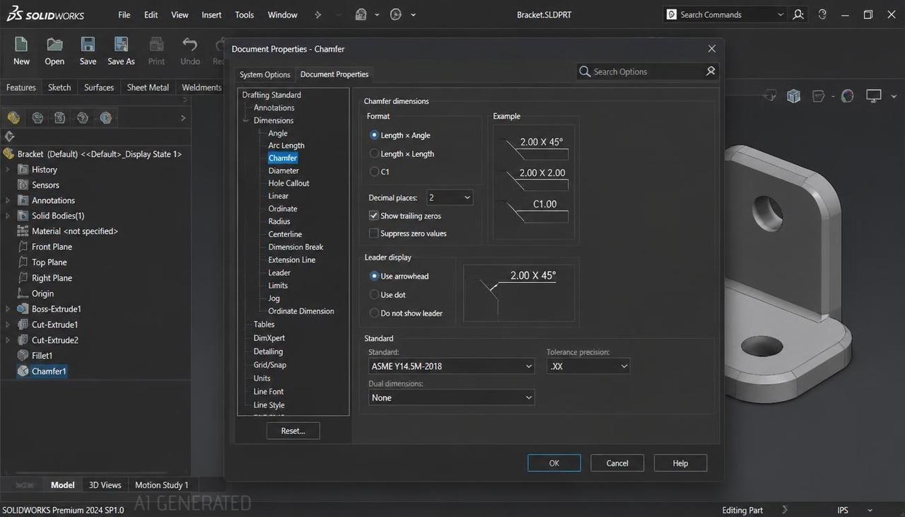
| C1 | 45° chamfer, one distance | 45° chamfers only; common on some customers' drawings The document defaults for leader display, text display and X display are in Tools > Options > Document Properties > Dimensions > Chamfer. The same page has the base chamfer dimension standard (ANSI, ISO, DIN, JIS, BSI, GOST or GB), the leader style and thickness, and the dimension value position. Set these in your drawing template, as described in our drawing template guide, so every drawing starts with the same format. Our guide to drawing symbols and standards covers which standard to pick, and our text and leaders guide covers editing the callout text when you need a note around it. |
Tolerance Options for Chamfer Dimensions
Which tolerance types a chamfer dimension accepts depends on your version of SolidWorks. The 2016 Help lists None, Bilateral and Symmetric. The 2025 Help adds Limit, MIN and MAX, and Fit and Fit with tolerance for linear dimensions only. Open the tolerance type list on a chamfer dimension in your version to see which of these it offers. For most drawings the general tolerance block covers chamfers, and a tolerance is written on the dimension only when the chamfer is functional.
JLCCAN Auto-Drawing generates standard views and dimension chains straight from your SolidWorks parts, so you can spend your time on engineering review, not repetitive setup
Free Download >
When the Value Reads Wrong
If the callout shows a number you did not expect, check these in order.
- Selection order. The chamfered edge goes first, the lead-in edge second. SolidWorks Help gives only this order. Users on the SolidWorks forum report that choosing a different lead-in edge, or reversing the order, can change the reading, but Help does not document it.
- The tool. A number such as 1.41 for a 1 mm chamfer means the dimension was taken with Smart Dimension on the angled edge. Delete it and use Chamfer Dimension.
- The text format. A callout that reads 1 × 1 where you expected 1 × 45° is a document setting, not a modelling error. Check Document Properties > Dimensions > Chamfer.
- The model. If the chamfer was made as a distance and distance feature rather than distance and angle, the angle is derived. Open the Chamfer feature in the part to see what it holds.
- The drawing standard. Changing the standard can change the base chamfer dimension standard, which changes how the callout is drawn.
FAQ
How do I dimension a chamfer in a SolidWorks drawing? Click Chamfer Dimension on the Dimensions/Relations toolbar or use Tools > Dimensions > Chamfer, select the chamfered edge, then one of the lead-in edges, and click to place the dimension.
Why does my chamfer dimension read the wrong value? Usually the dimension was taken with Smart Dimension on the angled edge, which measures the sloped face, or the edges were selected in the wrong order. Use Chamfer Dimension and select the chamfered edge first.
How do I change a chamfer dimension from 1 × 45° to C1? The text format is a document setting under Tools > Options > Document Properties > Dimensions > Chamfer. C1 applies to 45° chamfers only.
Can I add a tolerance to a chamfer dimension? Yes, within the types your version supports. The available types differ between versions, so check the Dimension PropertyManager in your own installation.
Popular Articles
Keep Learning
Engineering Drawing Examples: Annotated Part, Assembly, Exploded, Weldment and Sheet Metal Drawings
Quick answer: A good engineering drawing example shows more than the views. It shows how the views, dimensions, symbols, notes and title block work together for one specific part. The six examples below cover a machined part, a part with an inclined face, an assembly, an exploded assembly, a welded frame and a sheet metal part, and each one says why it is drawn the way it is. Use them as a pattern for your own drawings, or as exercises. Searching for engineering drawing examples mostly returns picture......
How to Export a SolidWorks Drawing to PDF, DXF and DWG (and Export Many at Once)
Quick answer: To export a SolidWorks drawing to PDF, use File > Save As, choose PDF as the type and set the options for colour, fonts and quality. For DXF or DWG, use File > Export As in newer versions (File > Save As in older ones), choose the type and set the export options, including whether a multi-sheet drawing goes to paper space. Most export problems come from the drawing's display quality, scale and fonts, not from the file type. The drawing is finished and checked, and now someone needs it in......
SolidWorks Weldment Drawing: Views, Cut List, Balloons, and Weld Symbols
Quick answer: A SolidWorks weldment drawing shows a welded frame in a few views of the whole weldment, a cut list that lists each structural member with its length and quantity, balloons tied to that list, and weld symbols that say how each joint is made. Build the views and the Weldment Cut List table from the weldment part, add balloons so their numbers follow the cut list, and bring in or add weld symbols last. The drawing is only as good as the cut list in the part, so check the properties and the......
Drawing Views in SolidWorks: Orthographic, Isometric, Section, Auxiliary, Detail, and Break Views
Quick answer: Drawing views are 2D pictures of a 3D model. Orthographic views (front, top, right) show true shapes and carry the dimensions, an isometric view shows the part's general form, and derived views handle special jobs: section views for the inside, auxiliary views for inclined faces, detail views for small features, and break and crop views for long or crowded views. In SolidWorks, you place a base view first and derive the others from it, which keeps them aligned and linked to their parent.......
SolidWorks Exploded View: Create It, Add Explode Lines, and Show It on a Drawing
Quick answer: An exploded view is built in the assembly, not in the drawing. Click Exploded View, add steps that move components along an axis, add explode lines with Explode Line Sketch, then on the drawing select a model view of the assembly and turn on Show in exploded or model break state. Balloons on that view read from the BOM as usual, and most missing explode lines come down to sketch display or the wrong configuration. The shop gets twelve part drawings and a pile of parts. Nothing says which......
Assembly Drawing vs Detail Drawing in SolidWorks: What Goes on Each, and How to Build the Assembly Drawing
Quick answer: An assembly drawing shows how the parts of a product fit together, with views, a bill of materials and balloons that link each part to its row. A detail drawing shows one part with everything needed to make it. In SolidWorks, you build the assembly drawing from the assembly, add a section view where it helps, insert the BOM and balloons, and add an exploded view when the reader needs the order of assembly (see our exploded view guide). The shop gets twelve part drawings and a pile of par......