SolidWorks Auxiliary View: When You Need One and How to Create It
9 min
- When You Need an Auxiliary View
- How to Create an Auxiliary View
- Partial Auxiliary View
- Arrow, Label and Alignment
- Dimensioning the Inclined Face
- Example: The Bracket With an Inclined Face
- Fixing the Usual Problems
- FAQ
Quick answer: Use an auxiliary view when a feature sits on a face that is tilted away from the standard views, so it appears shortened and cannot be dimensioned true. In SolidWorks, click Auxiliary View, select a reference edge on the inclined face that is not horizontal or vertical, and place the view. Crop it to the inclined face if the rest of the part would only repeat what the other views show.
The slot on the inclined face looks short because it is seen at an angle. The hole in it looks like an ellipse. The machinist asks for the real length, and the drawing cannot give it, because every number you can measure from the front view is shorter than the part. An auxiliary view is the view that fixes this, and it is a small one to add.
This guide covers when an auxiliary view is worth adding, how to create one, how to limit it to the inclined face, how the arrow and label work, and how to dimension the face once it is shown true. For the other view types, see our drawing views guide.
Key Takeaways
- An auxiliary view looks straight at an inclined face that appears foreshortened in the standard views, which makes true lengths and angles readable.
- The reference edge cannot be horizontal or vertical, or SolidWorks produces an ordinary projected view, and an auxiliary view cannot be created from a detail view.
- A partial auxiliary view is made by creating the auxiliary view and cropping it with a closed profile, which keeps the sheet uncluttered.
- Auto-Drawing does not add auxiliary views on parts, so this stays a manual step.
When You Need an Auxiliary View
In an orthographic projection, a face that is parallel to the view plane shows its true size, and a face tilted to it shows shortened. The amount follows the angle: a face tilted 30° from the view plane shows its length multiplied by the cosine of 30°, about 0.866. A 40 mm slot on that face measures 34.6 mm in the standard view, a hole on it appears as an ellipse, and nothing on the sheet tells the reader the real size.
An auxiliary view looks at the face along its normal, so the face appears in its true shape and size. SolidWorks Help describes it as similar to a projected view, unfolded normal to a reference edge in an existing view. Add one when two things are true: the inclined face carries features that matter (holes, slots, a boss, an engraved note), and those features need dimensions or inspection. If the inclined face is plain, the standard views and a note are enough, and an extra view only crowds the sheet.
How to Create an Auxiliary View
- Start the tool. Click Auxiliary View on the Drawing toolbar, or use Insert > Drawing View > Auxiliary. In the CommandManager the button sits on the Drawing tab, which some reseller guides call View Layout.
- Select the reference edge. Pick an edge of the inclined face in the parent view. It must not be horizontal or vertical, because SolidWorks Help says that would create a standard projection view instead. The edge can be a part edge, a silhouette edge, an axis or a sketched line.
- Place the view. As you move the pointer, SolidWorks previews the view if you selected Show contents while dragging drawing view. Click to place it. The view is unfolded perpendicular to the reference edge.
- Check the arrow and label in the PropertyManager (next section), and change the alignment if you need the view somewhere else.
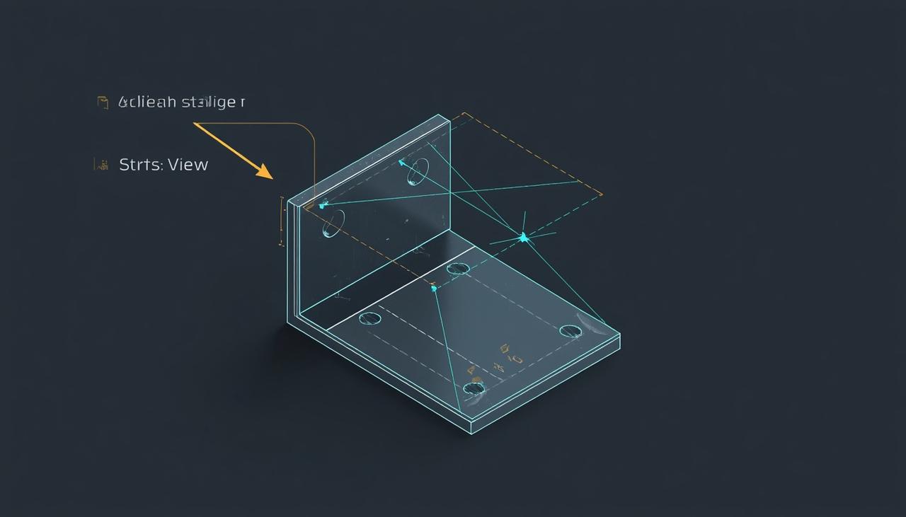
Two rules from SolidWorks Help save time. Auxiliary views are not available from detail views, so make them from a standard view. And if you used a sketched line as the reference, SolidWorks absorbs the sketch so you cannot delete it by accident. To edit it, select the auxiliary view and use Arrow in the PropertyManager, or edit the sketch.
When no edge is square to the face, add a sketched line in the parent view that is perpendicular to the direction you want, and use that line as the reference. This is a common way to get a view for a face that has no convenient edge.
Partial Auxiliary View
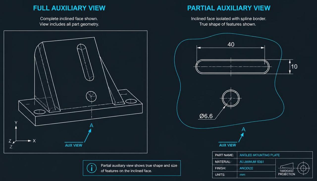
A full auxiliary view shows the whole part from the new direction, and most of it repeats what the other views already show. A partial auxiliary view keeps only the inclined face and what is on it. In SolidWorks you make it in two steps: create the auxiliary view, then sketch a closed profile around the inclined face on that view and use Crop View with the sketch selected, which hides everything outside the profile. SolidWorks Help describes Crop View in the same terms: a closed profile, usually a spline, with everything outside it hidden.
The result is easier to read and saves sheet space. Show only enough of the surrounding geometry for the reader to see how the face sits on the part, and keep break lines tidy. Hidden lines usually add nothing in a partial auxiliary view (see our guide to lines in drawings).
Arrow, Label and Alignment
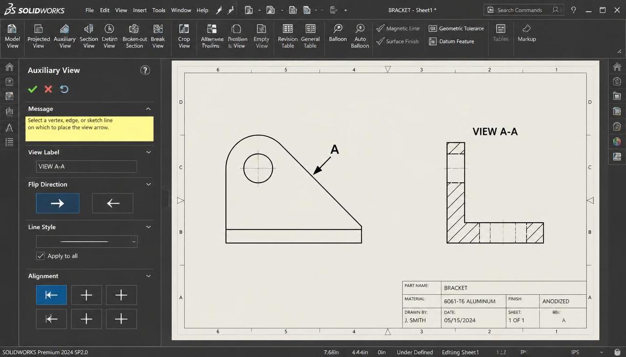
The Auxiliary View PropertyManager controls how the view is tied to its parent. Arrow shows a view arrow in the parent view (a set of arrows under the ANSI drafting standard) so the reader knows from which direction the view was taken. Flip direction reverses the arrow if the view looks the wrong way round. Label takes text that appears with both the parent view and the auxiliary view, and its display style is set under Tools > Options > Document Properties > View Labels > Auxiliary.
If you delete an auxiliary view, its letter becomes free. SolidWorks has an option to reuse the letters of deleted views, so the next view does not skip a letter. The option is Reuse view letters from deleted auxiliary, detail, and section views, under Tools > Options > System Options > Drawings, and it is off by default.
The view is aligned to its parent by default, in the same way as a projected view, which keeps it lined up with the edge it came from. To place it elsewhere, break the alignment from the right-click menu, as described in our drawing views guide, and restore it if the view drifts.
Dimensioning the Inclined Face
The point of the view is that the face now shows true, so dimension the face in the auxiliary view and not in the standard views. Hole diameters, slot lengths and widths, and the size of the face are all read correctly there. Dimensions that locate the face on the part, such as its distance from a datum, are usually clearer in the parent view where the angle shows.
Two habits keep the drawing consistent. Dimension each feature once, in the view where it appears true, as our SolidWorks dimensioning says. And remember that SolidWorks Help treats dimensions added in a drawing as reference dimensions, shown in parentheses by default, and the auxiliary view follows the same rule, so if the model's own dimensions are what you want, bring them in with Model Items or see our reference dimension guide for the difference.
Example: The Bracket With an Inclined Face
Take a bracket with a mounting face inclined at 30° to the front plane, carrying a 40 × 10 mm slot and a Ø6.6 hole. The numbers are invented for the example.
| View | What it shows | Why it is there |
|---|---|---|
| Front | The main profile and the inclined edge | Parent for the auxiliary view and the reference edge |
| Right | The height and the angle of the inclined face in profile | Dimensions the 30° and the face's position |
| Auxiliary, partial, from the inclined edge | The face in true shape with the slot and hole | Slot length and width, hole diameter, hole position on the face In the front view the slot would read 34.6 mm long, and the hole would be an ellipse. In the auxiliary view the slot is 40 mm, the hole is a circle, and each can carry a normal dimension. The drawing gets one extra view, cropped to the face, and the machinist has no number to work backwards from. |
JLCCAN Auto-Drawing generates standard views and dimension chains straight from your SolidWorks parts, so you can spend your time on engineering review, not repetitive setup
Free Download >
Fixing the Usual Problems
| Symptom | Likely cause | Fix |
|---|---|---|
| A projected view appears instead of an auxiliary one | The reference edge is horizontal or vertical | Select an inclined edge, or sketch a line to use as the reference |
| The tool will not work on a view | The parent is a detail view | Make the auxiliary view from a standard view |
| The view faces the wrong way | The arrow points the other way | Use Flip direction in the PropertyManager |
| The view shows the whole part | It is a full auxiliary view | Crop it to the inclined face |
| The view will not move freely | It is aligned to its parent | Break the alignment from the right-click menu |
| The label or letter is not what you expected | Label text or the letter order | Edit the Label in the PropertyManager, or reuse the letter of a deleted view |
| The sketched reference line disappeared | SolidWorks absorbed it into the view | Edit it through the Arrow option or the sketch |
| The auxiliary view shows too many hidden lines | The display style is Hidden Lines Visible | Change the view's display style |
FAQ
What is an auxiliary view in SolidWorks? A view unfolded perpendicular to a reference edge in an existing view, which shows an inclined face in its true shape and size.
How do I make an auxiliary view in SolidWorks? Click Auxiliary View, select an edge of the inclined face that is not horizontal or vertical, and click to place the view. It cannot be made from a detail view.
What can I use as the reference edge? A part edge, a silhouette edge, an axis or a sketched line. A horizontal or vertical edge would create a standard projection view instead.
How do I make a partial auxiliary view? Create the auxiliary view, sketch a closed profile around the inclined face on it, and use Crop View with the sketch selected.
Popular Articles
Keep Learning
Engineering Drawing Examples: Annotated Part, Assembly, Exploded, Weldment and Sheet Metal Drawings
Quick answer: A good engineering drawing example shows more than the views. It shows how the views, dimensions, symbols, notes and title block work together for one specific part. The six examples below cover a machined part, a part with an inclined face, an assembly, an exploded assembly, a welded frame and a sheet metal part, and each one says why it is drawn the way it is. Use them as a pattern for your own drawings, or as exercises. Searching for engineering drawing examples mostly returns picture......
How to Export a SolidWorks Drawing to PDF, DXF and DWG (and Export Many at Once)
Quick answer: To export a SolidWorks drawing to PDF, use File > Save As, choose PDF as the type and set the options for colour, fonts and quality. For DXF or DWG, use File > Export As in newer versions (File > Save As in older ones), choose the type and set the export options, including whether a multi-sheet drawing goes to paper space. Most export problems come from the drawing's display quality, scale and fonts, not from the file type. The drawing is finished and checked, and now someone needs it in......
SolidWorks Weldment Drawing: Views, Cut List, Balloons, and Weld Symbols
Quick answer: A SolidWorks weldment drawing shows a welded frame in a few views of the whole weldment, a cut list that lists each structural member with its length and quantity, balloons tied to that list, and weld symbols that say how each joint is made. Build the views and the Weldment Cut List table from the weldment part, add balloons so their numbers follow the cut list, and bring in or add weld symbols last. The drawing is only as good as the cut list in the part, so check the properties and the......
Drawing Views in SolidWorks: Orthographic, Isometric, Section, Auxiliary, Detail, and Break Views
Quick answer: Drawing views are 2D pictures of a 3D model. Orthographic views (front, top, right) show true shapes and carry the dimensions, an isometric view shows the part's general form, and derived views handle special jobs: section views for the inside, auxiliary views for inclined faces, detail views for small features, and break and crop views for long or crowded views. In SolidWorks, you place a base view first and derive the others from it, which keeps them aligned and linked to their parent.......
SolidWorks Exploded View: Create It, Add Explode Lines, and Show It on a Drawing
Quick answer: An exploded view is built in the assembly, not in the drawing. Click Exploded View, add steps that move components along an axis, add explode lines with Explode Line Sketch, then on the drawing select a model view of the assembly and turn on Show in exploded or model break state. Balloons on that view read from the BOM as usual, and most missing explode lines come down to sketch display or the wrong configuration. The shop gets twelve part drawings and a pile of parts. Nothing says which......
Assembly Drawing vs Detail Drawing in SolidWorks: What Goes on Each, and How to Build the Assembly Drawing
Quick answer: An assembly drawing shows how the parts of a product fit together, with views, a bill of materials and balloons that link each part to its row. A detail drawing shows one part with everything needed to make it. In SolidWorks, you build the assembly drawing from the assembly, add a section view where it helps, insert the BOM and balloons, and add an exploded view when the reader needs the order of assembly (see our exploded view guide). The shop gets twelve part drawings and a pile of par......