SolidWorks Drawing Sheets, Tables, Linked Properties, and Lost References: How to Add, Link, and Fix Them
15 min
- What a Drawing Depends On
- Add and Change Sheets
- Tables in a Drawing
- Link Material and Weight to the Model
- Model References: Open, Find, Replace
- Slow Drawings
- Example: A Three-Sheet Drawing Set
- Fixing the Usual Problems
- Where JLCCAN Fits
- Common Mistakes
- FAQ
Quick answer: A SolidWorks drawing is a set of sheets, each with a sheet format, plus references to the model files its views show and any tables or data you add. Add sheets from the sheet tab and set size and format in the sheet properties. Use General Tables for typed data and Insert > Object for Excel, because design tables belong to models. Link material and weight to model properties instead of typing them. When a drawing loses its model, use Find References, the References button in the Open dialog, or Replace Model.
The weight in the title block is right today. After the next revision, nobody updates it, and the drawing goes out with last month's number. Or the drawing opens with grey boxes and a cross where the views should be, because someone renamed a part. A drawing depends on things outside itself: its sheets, its models and its data. Most failures come from one of those links.
This guide covers adding sheets and changing paper size, putting tables and Excel data into a drawing, linking material and weight to the model, and fixing missing or wrong model references. It ends with a symptom table. For the surrounding workflow, see our guide to creating a SolidWorks 3D to 2D drawing.
Key Takeaways
- A drawing depends on its sheets, its model references, its linked properties and its tables, and finding which of them a problem belongs to comes before changing anything.
- Weight and material should be linked to model properties and not typed, and a weight field stays blank until the part has a material.
- Design tables belong to parts and assemblies, so a drawing uses a general table, an Excel object or a BOM instead.
- Renaming or moving files from inside SolidWorks, or with a tool that updates references, avoids the lost-reference problems that Windows Explorer causes.
What a Drawing Depends On
| Part of the drawing | What it is | Where it goes wrong |
|---|---|---|
| Sheet and sheet format | The paper, border and title block | Wrong size or format after a change |
| Model references | The part and assembly files behind the views | Renamed, moved or replaced files |
| Linked properties | Title block fields and notes that read the model | Property missing or blank |
| Tables and objects | Typed tables, Excel data, BOMs | Wrong table type, stale linked data When something on a drawing is wrong, find which row it belongs to before changing anything. |
Add and Change Sheets
A drawing file can hold several sheets, and each sheet can have its own format. SolidWorks Help describes the sheet format as the page size and orientation, standard text, borders and title blocks for a sheet.
- Add a sheet. Right-click the sheet tab at the bottom of the window and choose Add Sheet (or use the Insert menu). The new sheet takes the format of the drawing template unless you pick another. Menu wording varies by version.
- Change the paper size. Right-click the sheet and choose Properties. Under Sheet Format/Size, choose a standard size or browse to a different sheet format file. The border and title block change, and the views do not move, so check that they still fit the new sheet.
- Change the scale or projection. Both are in the same Sheet Properties dialog. New views use the sheet scale, and the type of projection is a sheet property, not part of the sheet format (see our drawing template guide).
- Different formats on different sheets. A first sheet with a full title block and later sheets with a short one is normal. Set the format per sheet.
- Units. Drawing units (for dimensions and notes) are set in Document Properties > Units and are independent of the units used to build the model. A model in inches can be dimensioned in millimetres on the drawing.
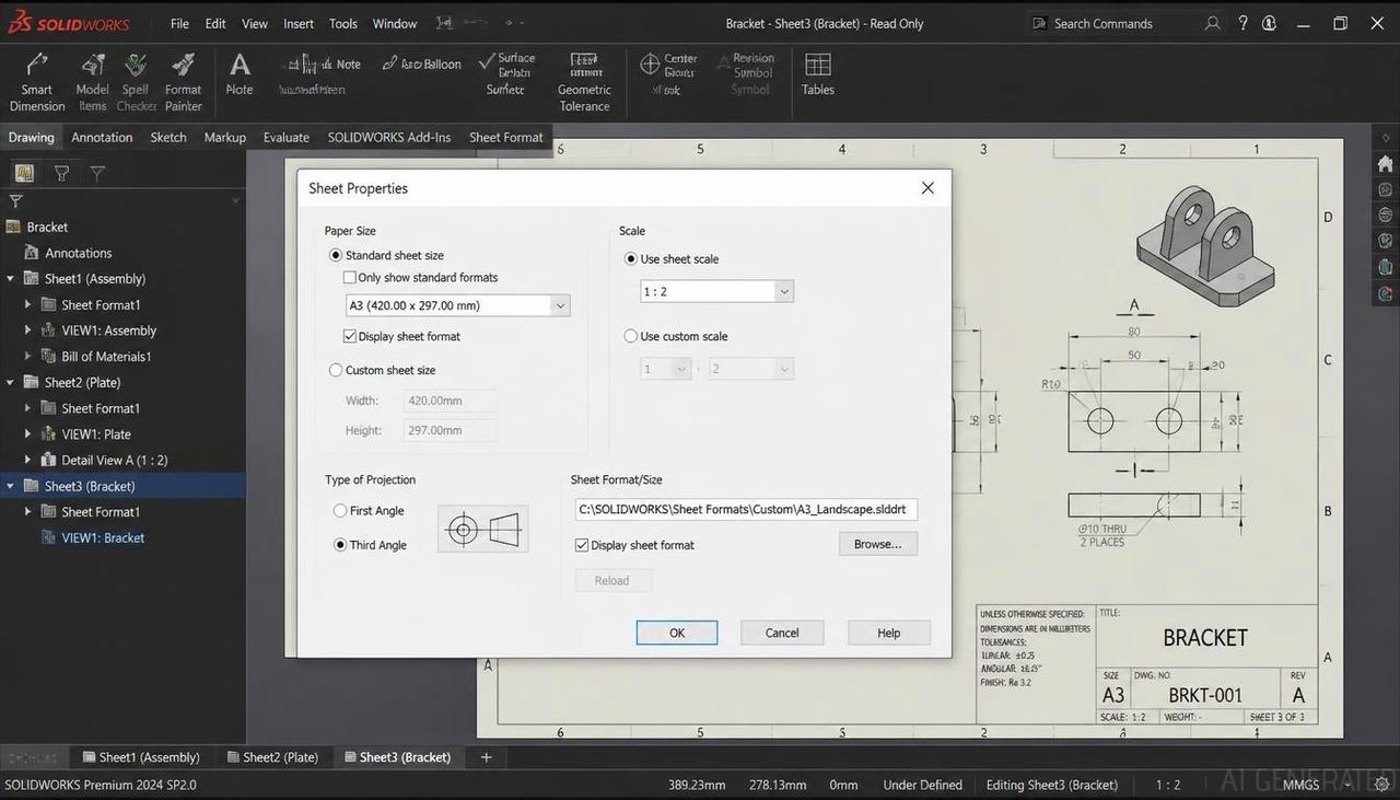
- If you are about to change a paper size on a drawing that has many views, move to the larger sheet first. Shrinking a sheet pushes views and dimensions outside the border, and rearranging them by hand is the slow part.
Tables in a Drawing
There are five ways to get tabular data into a drawing, and they are not interchangeable.
| You want | Use | Notes |
|---|---|---|
| A table you type yourself | General Table (Insert > Tables > General Table) | Every cell needs input. You can insert symbols and custom properties in cells |
| Parts list from an assembly | Bill of Materials (see our BOM guide) | Table-based or Excel-based, not both on one drawing |
| Holes with positions | Hole Table (see our Hole Wizard guide) | Measured from an origin datum |
| A cut list for a welded frame | Weldment Cut List (see our weldment drawing guide) | Built from the cut list in the weldment part, not typed |
| Data from an Excel file | Insert > Object | Embedded or linked, see below |
General tables
A general table is for data you type: revision lists, notes tables, tolerance charts. SolidWorks Help describes the same table functions as other tables, such as split, merge, sort and equations, and you can set a template and a file path for general table templates in Options. If you link a dimension's value to a cell, the cell shows the same elements as the original, including tolerance and extra text.
To edit one, double-click a cell and type. To change columns and rows, right-click the table.
Excel data
In a drawing, use Insert > Object to bring in an Excel worksheet. The two ways to do it behave differently.
- Embedded puts a copy of the data in the drawing. Editing it in the drawing does not change the source file, and changing the source does not change the drawing. You can resize the visible area by double-clicking the table.
- Linked keeps a connection to the source file. Edits to the source show in the drawing, and double-clicking the table opens Excel.
- Format the range in Excel before you embed or link it, so the table shows the cells you want.
- The usual rule is to embed for data that belongs to this drawing and link for data that is maintained elsewhere, such as a company-wide chart. If you link, keep the file in a shared path, or the drawing will show stale or empty data on another machine.
A note on design tables
People often search for "insert design table in solidworks drawing". SolidWorks Help describes a design table as an Excel sheet inserted into a part or assembly document (Insert > Tables > Design Table) that creates and controls configurations. It is a model feature, not a drawing table.
The data flows the other way: configurations created by a design table can show up in a drawing through the BOM, linked properties, or an Excel object. If you want to show a table of sizes for a family of parts in a drawing, make the table with General Table or Insert > Object, or use a configuration-aware BOM.
Link Material and Weight to the Model
A typed weight is a future error. Link it instead. The method is the one described in our drawing template guide, with two extra steps for mass.
- Set the property on the model. In the part, open File > Properties > Custom and create a property such as Weight. For its value, choose the SolidWorks mass property (SW-Mass) from the file properties list. For Material, use the material property (SW-Material) or assign a material to the part.
- Assign a material. Mass needs a density. A weight property stays blank until the part has a material, which is the commonest reason a weight field is empty.
- Link the note. In the drawing's sheet format, add a note, choose Link to Property, and select Model found here so SolidWorks reads the model's properties and not the drawing's. Pick Weight or Material. SolidWorks Help describes Model found here as reading the model of the view named in the sheet properties, which is the same source as the $PRPSHEET link in our template guide.
- Test it. Make a drawing from a part with a material and check the field.
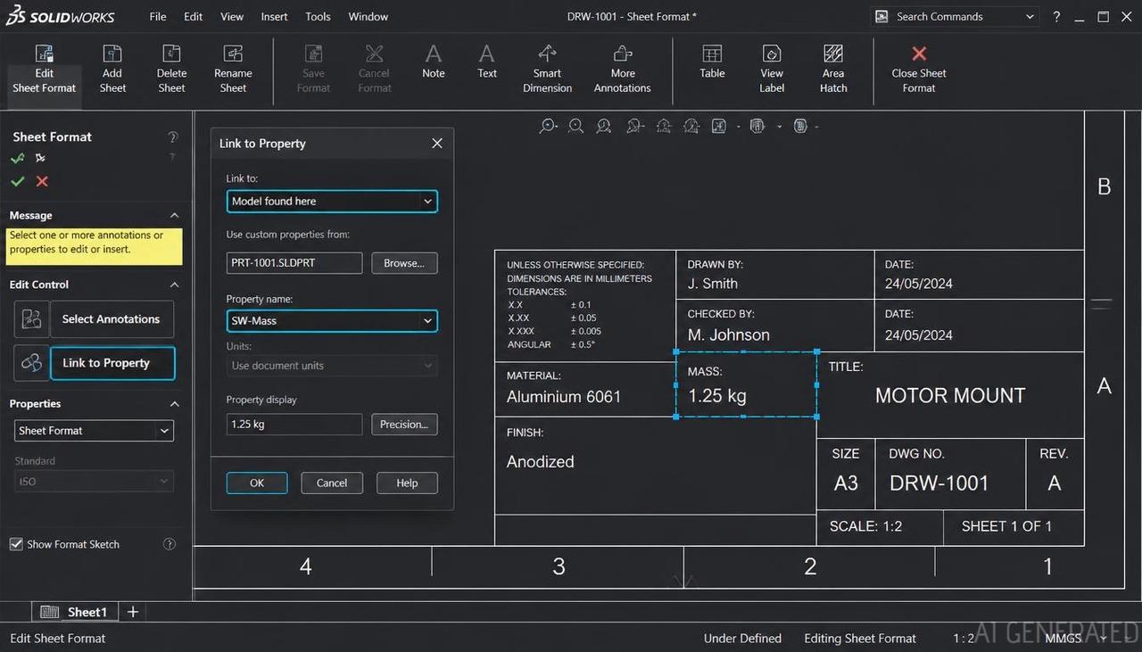
Two cautions. Linked mass uses the mass unit set in the model's Document Properties > Units (Mass/Section Properties), so a model set to pounds shows pounds, even if the drawing is metric. To show other units, SolidWorks resellers use an equation in the custom property that converts the value, then link the note to that property. And on a sheet with views of several models, the sheet properties decide which model the note reads, so check which view the sheet points to.
For assemblies, mass properties need the same care. A forum thread reports a title block where only some linked mass properties filled in for an assembly, so test each field on an assembly separately and not only on a part.
Model References: Open, Find, Replace
A drawing stores a reference to each model behind its views, not a copy. That is why the drawing updates when the model changes, and also why it breaks when the file moves.
| Task | How |
|---|---|
| Open the model of a view | Right-click the view and choose to open the part or assembly |
| Make a drawing from a model | In the part or assembly, use Make Drawing from Part/Assembly (see our drawing guide) |
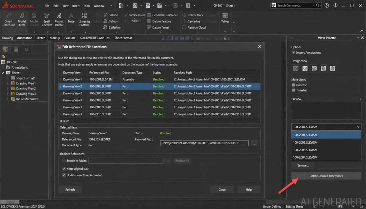
| See what a drawing references | File > Find References |
| Change references before opening | In the Open dialog, click References and replace a file |
| Swap the model in a view | Right-click the view, or Tools > Replace Model |
| Put views of several models on one drawing | Add views from the View Palette, picking each model from its drop-down Replace Model changes the file reference of selected views. SolidWorks Help says it works between parts and parts, assemblies and assemblies, and between parts and assemblies. Reseller notes add that replacing a part with an assembly (or the reverse) leaves dimensions dangling, so plan to redo some annotation. |
The phantom reference
A common puzzle: a drawing still lists a model in Find References, although no view shows it. The cause is the View Palette. When you use Make Drawing from Part or Assembly, SolidWorks puts the model in the palette, which creates a file reference even if you never insert a view. Open the View Palette in the Task Pane, select the unwanted model in its drop-down list and delete it with the red X. Then save, and the reference is gone from Find References and from PDM.
When the drawing cannot find its model
If views show as boxes with a cross, or a message says the file cannot be found, the reference points to a file that has moved, been renamed or replaced by one with a different path. In order:
- Open the drawing through the Open dialog and use the References button to point to the right file.
- If the file is in a new folder, add that folder to the search paths (Tools > Options > System Options > File Locations > Referenced Documents), and make sure Search file locations for external references is selected under System Options > External References, because SolidWorks only searches those folders when it is.
- Use Replace Model if the model was replaced by a different file.
- Keep a drawing and its models in the same project folder tree, so moving the folder moves all of them.
- The cheapest prevention is to rename and move files from inside SolidWorks (or a tool that updates references) and not in Windows Explorer.
Slow Drawings
Slow drawings, especially of large assemblies, come from loading and regenerating many components. Three things help.
- Draft quality for views you are not editing. Hidden edge changes need high quality, so switch back only where needed.
- Fewer views at once. Put views that need heavy regeneration on their own sheet.
- Do not load what you do not show. A drawing with a phantom reference loads that model too, so clean the View Palette.
- Large-assembly settings also change what loads and what is inserted automatically, for example automatic centerlines are not inserted in Large Assembly Mode (see our guide to lines in drawings).
Example: A Three-Sheet Drawing Set
Here is a set built from the plate and assembly used in our other guides.
| Sheet | Contents | Sheet format | Model reference | What is linked |
|---|---|---|---|---|
| 1 | Assembly with balloons and BOM | A3, full title block | Assembly | Part number, description from the assembly's properties |
| 2 | Plate detail with dimensions and hole callouts | A3, full title block | Plate part | Material and weight from the plate |
| 3 | Clamp arm detail | A4, short block | Clamp arm part | Part number, material Each sheet reads from its own model through its sheet properties. Rename the clamp arm outside SolidWorks and sheet 3 loses its references, while sheets 1 and 2 stay intact. |
Fixing the Usual Problems
| Symptom | Likely cause | Fix |
|---|---|---|
| Views show as boxes with a cross | Referenced file moved, renamed or not found | References button in the Open dialog, or add the folder to Referenced Documents (with Search file locations for external references selected) |
| Drawing lists a model that is not shown | Old reference left in the View Palette | Delete it with the red X in the View Palette, then save |
| Weight field is blank | No material assigned, or no Weight property | Assign a material and link Weight to SW-Mass |
| Title block shows the wrong part number | The sheet reads another model | Check the view named in the sheet properties |
| Weight in the wrong units | Model mass units differ from the drawing | Convert with an equation in the custom property |
| Paper size changed and views fell off the sheet | Views do not move with the sheet | Move to the larger sheet first, then rearrange |
| Cannot find Design Table in a drawing | Design tables are model features | Use General Table, Insert > Object or the BOM |
| Linked Excel table shows old data | Source file changed or moved | Keep the source in a shared path, update the link |
| Dimensions dangle after Replace Model | Part swapped for assembly or the reverse | Redo the affected dimensions |
| Drawing opens slowly | Large assembly, many views | Draft quality views, split sheets, clean the View Palette |
Where JLCCAN Fits
References, properties and renaming are where a plugin saves the most time, because every one of them multiplies across many files. JLCCAN's features page lists a Batch Manager with batch renaming, property editing, format conversion, title block replacement, part number parsing and drawing merging, plus a Rename with Drawing tool and a Property Manager.
The product team confirmed that Rename with Drawing keeps the drawing and assembly references intact when a part is renamed, and that Batch Manager can process a whole folder at once. According to the release notes, Rename with Drawing can save the renamed files to another path or rename within the current assembly, so you can choose between keeping the originals and changing them in place.
The habit is the same with or without a plugin: change names, properties and formats from inside a tool that knows about references, then check the first updated drawing before running the rest.
JLCCAN Auto-Drawing generates standard views and dimension chains straight from your SolidWorks parts, so you can spend your time on engineering review, not repetitive setup
Free Download >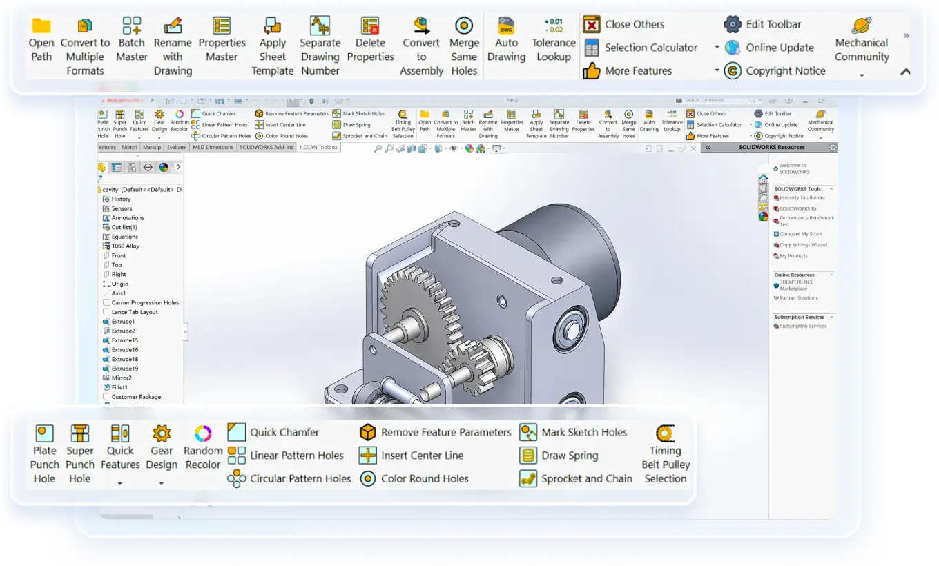
Common Mistakes
- Renaming or moving files in Windows Explorer. The drawing keeps pointing to the old name.
- Typing weight and material into the title block. They go stale at the next revision.
- Looking for Design Table in a drawing. It is a model feature.
- Linking Excel to a file on a personal drive. Nobody else sees the data.
- Shrinking a sheet with views already placed. Views fall outside the border.
- Leaving old references in the View Palette. They load, and they follow the drawing into PDM.
- Replacing a part with an assembly in a view and not checking dimensions. Many will dangle.
FAQ
How do I add a sheet to a SolidWorks drawing? Right-click the sheet tab at the bottom of the window and choose Add Sheet. Set its size and format in the sheet properties.
How do I change the paper size of a drawing? Right-click the sheet, choose Properties and pick a different standard size or sheet format. Check that the views still fit.
How do I insert an Excel table into a SolidWorks drawing? Use Insert > Object and choose to embed a copy or link to the file. Embedded data stays in the drawing, and linked data follows the source file.
Can I insert a design table in a SolidWorks drawing? Not as a drawing table. Design tables belong to parts and assemblies. In a drawing, use a General Table, an Excel object or a BOM.
How do I show weight and material in a SolidWorks drawing? Create Weight and Material properties on the model linked to the mass and material properties, assign a material, and link a note in the sheet format to them with Model found here.
What do I do when a drawing loses its part? Open the drawing with the References button in the Open dialog to point to the right file, add the folder to the search paths if needed, or use Replace Model.
Popular Articles
Keep Learning
Engineering Drawing Examples: Annotated Part, Assembly, Exploded, Weldment and Sheet Metal Drawings
Quick answer: A good engineering drawing example shows more than the views. It shows how the views, dimensions, symbols, notes and title block work together for one specific part. The six examples below cover a machined part, a part with an inclined face, an assembly, an exploded assembly, a welded frame and a sheet metal part, and each one says why it is drawn the way it is. Use them as a pattern for your own drawings, or as exercises. Searching for engineering drawing examples mostly returns picture......
How to Export a SolidWorks Drawing to PDF, DXF and DWG (and Export Many at Once)
Quick answer: To export a SolidWorks drawing to PDF, use File > Save As, choose PDF as the type and set the options for colour, fonts and quality. For DXF or DWG, use File > Export As in newer versions (File > Save As in older ones), choose the type and set the export options, including whether a multi-sheet drawing goes to paper space. Most export problems come from the drawing's display quality, scale and fonts, not from the file type. The drawing is finished and checked, and now someone needs it in......
SolidWorks Weldment Drawing: Views, Cut List, Balloons, and Weld Symbols
Quick answer: A SolidWorks weldment drawing shows a welded frame in a few views of the whole weldment, a cut list that lists each structural member with its length and quantity, balloons tied to that list, and weld symbols that say how each joint is made. Build the views and the Weldment Cut List table from the weldment part, add balloons so their numbers follow the cut list, and bring in or add weld symbols last. The drawing is only as good as the cut list in the part, so check the properties and the......
Drawing Views in SolidWorks: Orthographic, Isometric, Section, Auxiliary, Detail, and Break Views
Quick answer: Drawing views are 2D pictures of a 3D model. Orthographic views (front, top, right) show true shapes and carry the dimensions, an isometric view shows the part's general form, and derived views handle special jobs: section views for the inside, auxiliary views for inclined faces, detail views for small features, and break and crop views for long or crowded views. In SolidWorks, you place a base view first and derive the others from it, which keeps them aligned and linked to their parent.......
SolidWorks Exploded View: Create It, Add Explode Lines, and Show It on a Drawing
Quick answer: An exploded view is built in the assembly, not in the drawing. Click Exploded View, add steps that move components along an axis, add explode lines with Explode Line Sketch, then on the drawing select a model view of the assembly and turn on Show in exploded or model break state. Balloons on that view read from the BOM as usual, and most missing explode lines come down to sketch display or the wrong configuration. The shop gets twelve part drawings and a pile of parts. Nothing says which......
Assembly Drawing vs Detail Drawing in SolidWorks: What Goes on Each, and How to Build the Assembly Drawing
Quick answer: An assembly drawing shows how the parts of a product fit together, with views, a bill of materials and balloons that link each part to its row. A detail drawing shows one part with everything needed to make it. In SolidWorks, you build the assembly drawing from the assembly, add a section view where it helps, insert the BOM and balloons, and add an exploded view when the reader needs the order of assembly (see our exploded view guide). The shop gets twelve part drawings and a pile of par......